A modern repacement will be physically smaller, so you could do what the radio restorers do - clean out the contents of the old can then fit the replacement cap inside.
A modern repacement will be physically smaller, so you could do what the radio restorers do - clean out the contents of the old can then fit the replacement cap inside.
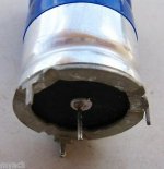
As i don't know what is used (old electrolytic) i prefer not to open this.😉
Do you want it to look like stock or just want to get it up and working? The 3 pins in the outside are the grounds. To use a new model with the same specs, with just 2 pins. You would just make a jumper wire to go to all 3 pins on the board. All 3 must be used, easy thing to do.
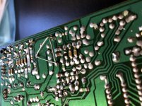
Look on the board, the three ground points may already be connected together by copper tracery. Measure the space between the center pin and one of the side pins. Now compare that to available lead spacing on new parts. If there are not other parts crowding around, You might get away with just installing the new part into two of the old holes.
Do you want it to look like stock or just want to get it up and working? The 3 pins in the outside are the grounds. To use a new model with the same specs, with just 2 pins. You would just make a jumper wire to go to all 3 pins on the board. All 3 must be used, easy thing to do.
This is exactly what I was hoping I could do. Thanks.
A modern repacement will be physically smaller, so you could do what the radio restorers do - clean out the contents of the old can then fit the replacement cap inside.
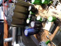
The new replacement is actually the same size. Just a couple mm shorter.
From a Philips CD player by any chance?
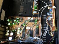
This one is from a Mission PCM CD player. But that CD player is based upon the Philips CD 650 w/CDM2/10 mech.
Agree and add: since the new cap will be shaky compared to the old 4 pin one, be certain to firmly fix it with a generous silicone bead around its base fixing its body to PCB to avoid flexing legs which will eventually break them.
Or good hot glue.
I usually preheat PCB a little with a heat gun so glue "wets" and sticks better.
Or good hot glue.
I usually preheat PCB a little with a heat gun so glue "wets" and sticks better.
This one is from a Mission PCM CD player. But that CD player is based upon the Philips CD 650 w/CDM2/10 mech.
Thought it had that look about it 🙂 A standard modern part will be fine but try and choose one that is as big as will physically fit as large parts often have better ripple current ratings than small ones. Even better, look at the data sheets.
Do you want it to look like stock or just want to get it up and working? The 3 pins in the outside are the grounds. To use a new model with the same specs, with just 2 pins. You would just make a jumper wire to go to all 3 pins on the board. All 3 must be used, easy thing to do.
Thanks for that, worked like a charm! Completely recapped and sounding great! .. and holy crap does it ever read discs fast now!
Attachments

Thought it had that look about it 🙂 A standard modern part will be fine but try and choose one that is as big as will physically fit as large parts often have better ripple current ratings than small ones. Even better, look at the data sheets.
The new one is just a couple mm shorter than the old one, same size otherwise 🙂
 should be fine.
Agree and add: since the new cap will be shaky compared to the old 4 pin one, be certain to firmly fix it with a generous silicone bead around its base fixing its body to PCB to avoid flexing legs which will eventually break them.
Or good hot glue.
I usually preheat PCB a little with a heat gun so glue "wets" and sticks better.
Its pretty solid as it sit flat right against the board. I may add a bit of hot glue later on just in case. Good tip! Thanks.
Attachments

- Home
- Design & Build
- Parts
- Trying to track down old cap.