Do you now have inverting amplifiers? Because of the feedback around the second stage a sign error will make a huge difference in gain.
PS why bother to solve the wrong circuit? Why not look at a circuit which will actually work?
In fact the stages are inverting. In this case a positive going input results in an increasing anode current which is a decreasing va but an increasing ia*Ra.
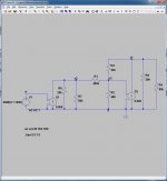
I you run a transient analysis you will notice that v1 and v2 are 180 degrees out of phase. In the picture I ajusted R2 to get an almost identical amplitude.
Attachments
I don't know what you are doing wrong, but if an impossible circuit appears to simulate OK then in some critical matter it does not accord with reality.
Put aside all the detailed calculations, and the simulations. Just look at the circuit. Given infinite stage gain in the second stage the phase splitter voltage gain would be 20k/400k = 0.05. Under these 'ideal' conditions the value of R2 does not matter as it merely shunts a virtual ground. For finite stage gain R2 attenuates the signal further so we know that any correct calculation or simulation must give a gain of less than 0.05.
Put aside all the detailed calculations, and the simulations. Just look at the circuit. Given infinite stage gain in the second stage the phase splitter voltage gain would be 20k/400k = 0.05. Under these 'ideal' conditions the value of R2 does not matter as it merely shunts a virtual ground. For finite stage gain R2 attenuates the signal further so we know that any correct calculation or simulation must give a gain of less than 0.05.
Nope, your schematic is still wrong. You've got your current sources the wrong way round. This way, the feedback resistor is causing the flip is phase you see, but check the phase between your signal source and the first stage for example, they are in phase, which is wrong.
Altering the schematic (flip the input terminals or make the arrow point downwards) to make it amplify correctly gives the exact same result as the one with the voltage source.
Could it be the values of R1 and R3 are swapped in the original schematic?
Altering the schematic (flip the input terminals or make the arrow point downwards) to make it amplify correctly gives the exact same result as the one with the voltage source.
Could it be the values of R1 and R3 are swapped in the original schematic?
Last edited:
R1 and R3 swap is a good idea. That would result in a working, but somewhat daft, circuit which looks superficially like an anode follower but has so little negative feedback that it is actually just an attenuator followed by an inverting gain stage.
I just tried 20467/467 - this is 43.8 - rather close to the stage gain of 44?
Well done, Mr. Funk - I think you have solved the mystery!
I just tried 20467/467 - this is 43.8 - rather close to the stage gain of 44?
Well done, Mr. Funk - I think you have solved the mystery!
Well, I am now convinced that the values the author gave R1=400k ; R2= 467 (his answer) and R3=20k cannot fulfil v2=-v1.
But one would expect a negative value of R2 or so when solving the derived equation.
DF96 already wrote that the factor A0 should have a negative sign, so I will have a closer look concerning 'signs' to see if I made some mistake in that way.
But one would expect a negative value of R2 or so when solving the derived equation.
DF96 already wrote that the factor A0 should have a negative sign, so I will have a closer look concerning 'signs' to see if I made some mistake in that way.
Just to clear up any possible confusion, my post 8 was written on the false assumption that post 7 was an admission that Merlin was the book author. I now see that I had jumped to a wrong conclusion so I apologise for any confusion. I must admit I was surprised that he had allegedly made such an error as his writing is usually reliable.
Could we be told where the daft circuit appears, and who the author is?
In the meantime, please read post 8 as remarks to the unknown author.
Could we be told where the daft circuit appears, and who the author is?
In the meantime, please read post 8 as remarks to the unknown author.
Just to clear up any possible confusion, my post 8 was written on the false assumption that post 7 was an admission that Merlin was the book author. I now see that I had jumped to a wrong conclusion so I apologise for any confusion. I must admit I was surprised that he had allegedly made such an error as his writing is usually reliable.
Could we be told where the daft circuit appears, and who the author is?
In the meantime, please read post 8 as remarks to the unknown author.
Wait, so Merlinb is NOT Merlin Blencowe??
The textbook I am referring to is from an in Holland well known author A.J. Sietsma:'Grondslagen van de Radiotechniek Deel I'.
It is written in the Dutch language and was in the fifty's and sixty's of the last century a standard book for vacuum tube theory. He also wrote a part II and two other standard works concerning semiconductors electronics.
Those books were widely used on schools for teaching electronics (on mine for instance)in those days.
In these books he included problems you had to solve at the end of a particular chapter.
My experience is that almost every problem you have to solve in this book is a sound one. It took a lot of time for me to admit that the problem was not my inability to solve this particular problem but some kind of printing error or schematic error on his side).
The remark you wrote in post 8 and if I understand you correctly:
I think you are right when an op amp is used which has an almost infinite open loop gain. But in case of a triode with a relatively low open loop gain, a resistor between grid and ground (R2)causes current to flow through it (there is no 'virtual ground' as is the case of an op amp in inverting configuration).So the current through the input resistor(R1) and feedback resistor(R3) do not necessarily have similar values.
But again I can misunderstand your comment in post 8.
Yes, with finite gain and/or significant input impedance (R2) the signal currents in the input and feedback resistors may no longer be almost equal.
What this thread shows is that experts, even those who write popular textbooks, sometimes get things wrong. Hence quoting an expert, as some like to do (see other threads), does not settle an argument. On the other hand, ignoring established science (see other threads) also does not settle an argument. Correctly applying established science is the way to settle an issue in audio electronics.
There appear to be two errors here:
1. A daft phase splitter circuit with matching attenuation and gain, but almost no feedback, is presented as an example of an anode follower.
2. Two resistors get swapped over, possibly by the printer, but nobody spots this during the proofreading.
But is Merlinb 'Merlin Blencowe' or isn't he??
Pretty cool to look at a 60 year old book with fresh eyes and discover these kind errors. Who knows how many peaople have broken their heads over this schematic.
Pretty cool to look at a 60 year old book with fresh eyes and discover these kind errors. Who knows how many peaople have broken their heads over this schematic.
Assuming a circuit works, and then doing the arithmetic to get component values, is a valid way of analysing provided that the assumption is correct. You have mixed up feedback current and input current.
Actually I did not mix up feedback and input current, but I did carlessly miss out a minus sign! How embarassing. Let's try again:
First estimate the open-loop gain, noting that the load on the valve is roughly Ra||R3 = 16k.
A = 100 * 16 / (16 + 20) = 44
Now assume +44V at the anode, -1V at the grid and -44V input.
Current in R3 = 45/20k = 2.25mA
Current in R1 = 43/400k = 108uA
Therefore current in R2 = 2.25 - 0.108 = 2.142mA
Since there is 1V across it, its value must be -1/2.142mA = -467 ohms.
I think you'll find this will indeed give unity gain. Farnell seem to be out of stock on negative resistors though 😕
And yes, Funk1980, I am Merlin Blencowe.
Or am I?
Last edited:
Hahaha awesome. Dude, your book 'Designing Tube preamps for guitar and bass' was my introduction to tube amp design about 5 years ago. The level was perfect for me to get started. And I just finished a headphone amp based on your SRPP paper. When I'm in Britain I'll buy you a beer.
Too bad there are no negative resistors. Would make life a lot easier.
Too bad there are no negative resistors. Would make life a lot easier.
I wrote:
But one would expect a negative value of R2 or so when solving the derived equation.
And Merlin B got:
Since there is 1V across it, its value must be -1/2.142mA = -467 ohms.
But one would expect a negative value of R2 or so when solving the derived equation.
And Merlin B got:
Since there is 1V across it, its value must be -1/2.142mA = -467 ohms.
Which should have been a dead giveaway that the circuit with the given values and parameters is impossible.I wrote:
But one would expect a negative value of R2 or so when solving the derived equation.
And Merlin B got:
Since there is 1V across it, its value must be -1/2.142mA = -467 ohms.
But is Merlinb 'Merlin Blencowe' or isn't he??
I now think he is not.........😕
Joe, he was just gently teasing, he is indeed Merlin Blencowe. 😀
kevin,
Then why does he not respond on a pm I wrote to him concerning
an article he published....😕
Joe.
- Status
- Not open for further replies.
- Home
- Amplifiers
- Tubes / Valves
- Trying to solve a Plate Follower Problem