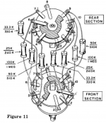
I'm working on this old Heathkit IG-72, and I'm trying to understand the rotary switches used for frequency selection. Were these switches standard types back in the day, or would each one be custom designed to-purpose? Attached is a picture of one of the switches, and it's exploded diagram. I kinda understand what's going on, but I'm still confused.
Attachments
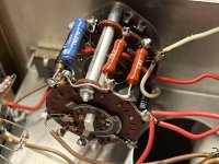
It's a standard switch, but a custom contact configuration for the mfr aplication.
Try looking at the schematic instead of the pictorial.
Looks like the bridged-T oscillator feedback resistors are switched to change the frequency.
But the switching is not explicitly shown on the schematic.
Try looking at the schematic instead of the pictorial.
Looks like the bridged-T oscillator feedback resistors are switched to change the frequency.
But the switching is not explicitly shown on the schematic.
Attachments
Last edited:
The source-selector on Hi-Fi, and those Heathkits, were semi-custom switches.
You used to be able to telex your contact-code to several switch makers, get quotes, confirm the order.
That business is all gone now.
These rotary switches: do you know the lamp timer with a round knob and 24 or 96 sliders?

Centralab and the others must have had like that but with hardened sharpened cutters with at least two cut-shapes. Set the cutters to the code and it will punch metal rotor-contacts. There was already a shoe-machine to punch lace eyelets and fancy buttons; put this cutter in and it will punch metal until the order is filled.
If you broke the switch, buy another for-parts IG on the Bay.
You used to be able to telex your contact-code to several switch makers, get quotes, confirm the order.
That business is all gone now.
These rotary switches: do you know the lamp timer with a round knob and 24 or 96 sliders?
Centralab and the others must have had like that but with hardened sharpened cutters with at least two cut-shapes. Set the cutters to the code and it will punch metal rotor-contacts. There was already a shoe-machine to punch lace eyelets and fancy buttons; put this cutter in and it will punch metal until the order is filled.
If you broke the switch, buy another for-parts IG on the Bay.
The rotary switch you posted is not plain vanilla AT ALL and very much doubt you can find a similar one over-the-counter unless somebody kept one in his cellar for decades.I'm working on this old Heathkit IG-72, and I'm trying to understand the rotary switches used for frequency selection. Were these switches standard types back in the day, or would each one be custom designed to-purpose? Attached is a picture of one of the switches, and it's exploded diagram. I kinda understand what's going on, but I'm still confused.
Clearly it connects MANY contacts at the same time, many make-before-break, or "at the same time at different points"
Most dedicated type I saw in a long time.
Of course, way back then, Manufacturer custom ordered what he needed plus a "servicing surplus", say 5% or even 10% more and he could sell you one from his stash.
But when/if stash dried up or 30 years passed without orders, I bet remainders were ditched mercilessly.
That’s what I was afraid of… one of the rotary contact plates came apart. I’ve glued it, and I’ll keep my fingers crossed that it holds. If not, I think I understand the circuit well enough to replicate it with a standards part, I’ll just need more resistors.
Hope it holds 🙂
Thyat said, didn´t dig deep (or at all) but I´m certain you can duplicate it with a couple switches, most probably a 3 or 4 wafer type, where you interconnect proper terminals as needed.
Just hope you have space enough for it 😉
Thyat said, didn´t dig deep (or at all) but I´m certain you can duplicate it with a couple switches, most probably a 3 or 4 wafer type, where you interconnect proper terminals as needed.
Just hope you have space enough for it 😉
Hope it holds 🙂
Thyat said, didn´t dig deep (or at all) but I´m certain you can duplicate it with a couple switches, most probably a 3 or 4 wafer type, where you interconnect proper terminals as needed.
Just hope you have space enough for it 😉
Thanks! So do I. Fingers crossed!
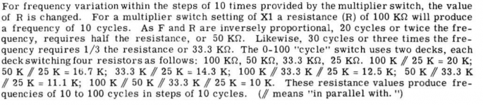
The switch construction is designed to produce 10 resistance values via various combinations of four resistors (see attached). At worse I should be able to use a switch with 10 poles and just "brute force" each positional value. It's not like resistors are expensive.
Attachments
Good.
Way back then parts were expensive, so to save money on NASA quality 1% resistors, they went through hoops to use just 4 of them, switch complexity be d*mned.
Today?
If that´s all you need you can simply use a 10 position switch and .... gosh! .... TEN 1% resistors 🙂
If I don´t remember wrong, it used a Bridged T or Twin T for frequency selection, so you will probably need a 2 wafer switch, one for each "T" side.
- Home
- Design & Build
- Parts
- Trying to identify rotary switch type from Heathkit IG-72 signal generator