Wooo!!! Noise is almost gone now . Switching the AC ends on one bridge rectifier made the biggest difference. When nothing is connected to the input terminals there is almost 0 hum, its even hard to notice with the ear right next to the speaker. Much much better than before! This is with both channels running. Shorting the DC ground to AC ground slightly reduces noise, it didn't make any different before !
I have new power supply caps on order with screw mount terminals, it will make it easier for me to mount multiple wire ends to same point. Hopefully that will get rid of all the noise !
Thank you everyone who made suggestions!
I have new power supply caps on order with screw mount terminals, it will make it easier for me to mount multiple wire ends to same point. Hopefully that will get rid of all the noise !
Thank you everyone who made suggestions!
so close, just not there yet
Are you people tired yet ? 🙂
Today I got my new PSU caps and thought I finally got rid off all the noise that was present. I really think I am getting closer to finding the problem, well I hope I do 🙂
Here is what we have on the table now. My amplifier is now dead silent when nothing is connected to the Inputs. I can place my ears right next to the speakers (1" away) and there is no noise at all. The same thing happens if I attach RCA cables to the amplifier, but leave the other end just hanging. Its also dead silent if I short the other end of RCA cables.
EDIT - ( Here is where I still have a problem, when the RCA grounds are connected together there is noise. When this happens noise gets in both channels, not just one channel. )
Actually I just found out that noise is present when RCA ends are connected to the source. Not when RCA grounds are shorted!
I have AC ground connected to the chassis, then DC ground is connected to the AC ground via 10ohm resistor. This makes the amplifier dead silent when nothing is connected to the inputs. I tried disconnected DC ground from the AC, and also removing AC ground completely and it didn't make any positive difference.
So, what should I do next ?
Picture if it helps at all, please ask if you have any questions :Click here
More information.
If one RCA jack is connected to the source amplifier is still DEAD silent. It's when second RCA jack is connected noise is present. Also, it doesn't matter if the second RCA jack signal wire only is connected, with the ground (shield) floating.
More information.
If one RCA jack is connected to the source amplifier is still DEAD silent. It's when second RCA jack is connected noise is present. Also, it doesn't matter if the second RCA jack signal wire only is connected, with the ground (shield) floating.
Finally, I tried running RCA grounds directly to Vground, same point where speaker grounds are connected. That only made problems worse, it became more noisy.
This will be my last multi-channel single chassis amplifier for sure 🙂
This will be my last multi-channel single chassis amplifier for sure 🙂
Re: Connect the power ground
Dinesh,
Since you have the same amplifier, did you use Rod Elliot boards or made your own ? How do you have your RCA grounds connected ?
Thats the only thing left, but then again I tried running a wire directly from Star ground to rca jacks and it only made the problem worse
dine1967 said:Jean,
I built the p3a and have a dual power supply as you have indicated in one of your posts.All the ground should return to a single point on the capacitor bank. The wires include ground from PCB, the speaker returns and the power. How ever the power ground passes through 2 6amp diodes, an AC rated capacitor and a 10ohm, 5 watt resistor before terminating at the star ground. I have no hum from this arrangement. You could also check if the wiring is symetrical from the secondry of the transformer to the two rectifier bridges. Hope this help. Don't skip the power earth.... It is there for safety.
Dinesh
Dinesh,
Since you have the same amplifier, did you use Rod Elliot boards or made your own ? How do you have your RCA grounds connected ?
Thats the only thing left, but then again I tried running a wire directly from Star ground to rca jacks and it only made the problem worse
Thats the only thing left, but then again I tried running a wire directly from Star ground to rca jacks and it only made the problem worse
maybe it is a dumb question, but did you remove the connection between PCB and input RCA ground while doing this test?
Cheers
Andrea
PS You could try Aleph's suggested wiring scheme, you can easily find it on Pass Labs forum
Andrea - Yes I sure did. It works great, its dead silent by itself but connect the rca jacks and noise is back 🙁
Another thing: looking at the picture your transformer is in the midde of the loop created by the input grounds, try swapping it with the capacitors.
Cheers
Andrea
Cheers
Andrea
Andrea,
You mean swap the locations of the Transformer and Capacitors in the chassis ? Hmmm, I could remove the transformer and set it outside the chassis by extending only couple wires .
You mean swap the locations of the Transformer and Capacitors in the chassis ? Hmmm, I could remove the transformer and set it outside the chassis by extending only couple wires .
I mean swapping their position.
Moving the trafo outside the chassis can be helpful, but only if you put it outsude the loop made by the grounds.
Cheers
Andrea
Moving the trafo outside the chassis can be helpful, but only if you put it outsude the loop made by the grounds.
Cheers
Andrea
Hi, Jean
Grounding scheme in multichannel amps isn't simple task. Amps aren't close together placed, ground wires are to long. etc. Now you have problem with grounding loop "source 1 ground-input RCA- one amp ground- second amp ground- and back to source 2 ground. Optimal solution here is using audio transformer with lifted ground, but this is expensive way.
Anyway try this:
- disconnect grounds of shielded input wires
- connect together grounds of input RCAs with heavy wire (speaker multistranded 4mm2 for example)
- connect with this wire this new global input ground to ground plate on caps
- change ground wire to each amp (your black wires on picture) with doubled heavy wire 4mm2
Once again, VERY important is that this connection are made with very heavy wire.
I have not picture of PCB, but if this suggestion will fail, only what you can do is wiring and rearranging slightly PCBs according my idea posted earlier on this thread.
I see on your picture one black wire from ground to front side. What purpose has this wire? If is ground connection to chassis, this is wrong place; try connecting this wire near input AC mains connector, or lift this wire at all.
Regards
Jean said:Picture if it helps at all, please ask if you have any questions :Click here
Jean -
Refer back to the earlier post by moamps with the illustration of how to wire the common line (that is, the capacitor bank common). On his picture, he very wisely has the common for the amplifier removed a slight distance from the capacitor connections themselves! This is critical because there will be extremely large (very high peak to average, that is) current pulses passing through the common connection. Connecting your amplifiers to the capacitor bolts is sure to make the current-pulse induced voltage drops "part of the signal." Drill a hole in the center of the bus bar at the forward edge to place a bolt and nut where all of the load-side common connections can be made. This subtle change will likely improve things incredibly.
(nice job, Moamps!)
Thanks for all the suggestions. Today I tried connecting grounds at a different location like suggested. It didn't make any difference, so the only thing left now is to rewire signal wires.
In the last minute I managed to blow one channel, then afte switching fuses on that one channel I then managed to fry one of my scan speak 8565-01s .
Maybe its time for another amp.
In the last minute I managed to blow one channel, then afte switching fuses on that one channel I then managed to fry one of my scan speak 8565-01s .
Maybe its time for another amp.
Jean said:Thanks for all the suggestions. Today I tried connecting grounds at a different location like suggested. It didn't make any difference, so the only thing left now is to rewire signal wires.
In the last minute I managed to blow one channel, then afte switching fuses on that one channel I then managed to fry one of my scan speak 8565-01s .
Maybe its time for another amp.
Hi,
I'm sorry about your accident with the amp, especially that you blew a pricey speaker. BTW, it is an unspoken rule and common procedure that new DIY amps should be tried out on cheap speakers and that one should check DC offset on the output terminals before connecting the speakers. Once the amp has been built, it doesn't hurt to leave it loaded with such a cheap speaker for a few days so that various amp parameters are allowed to stabilize and to safeguard against any shortcomings that may cause malfunction in the long run.
When building an amp, the most critical moment is switching it on for the first time. More experienced (and those with more resources available to them) DIY-ers would use an autotransformer (variac) and gradually increase the voltage to the nominal level, keeping an eye on the basic amp parameters while doing that. This enables them to spot possible mistakes and prevent the parts from being destroyed. When testing low-power amps, one might find symmetrical bench power supply with output current limiting capabilities very useful as they make it virtually impossible to blow up anything.
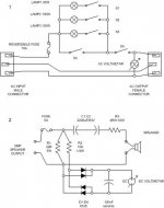
In my early DIY days, when I had nothing of my current equipment available to me, I built myself a simple circuit which I used to insert between a wall outlet and the amp I was testing/building, as can be seen on Figure 1.
Using the mains lamps 1-3 and the corresponding switcher combinations S1-S4, transformer pre-load is set. S5 serves as the main power-on switch while the AC voltmeter is connected to the output connector in order to monitor output voltage. By using this circuit I was able to replace variac and gradually increase working voltage of the amp, which proved to be very useful for servicing other equipment as well.
Also, your amp was damaged probably because a huge DC offset appeared on the amp's output. To avoid this, I used to insert a simple circuit (Figure 2) between the amp and the speaker so as to protect the speaker from damage.
Caps C1 and C2 isolate the speaker from a possible DC offset, R3 limits maximum speaker power (even if the amp becomes unstable), R1 serves as the minimum amp load. The bottom part of the circuit (diodes, caps) serves as a multi-purpose DC-AC voltmeter. It shows reading if DC offset appeares on the amp output (exceeding 0.7V) or if the amp oscillates.
Regards
Attachments
moaps, I think its was a stupid mistake on my part. Not a fault of the amplifier at all. I shorted one of outputs while switching cables, and it blew rail fuses on one circuit board and left the ac fuse alone. At that point, only one channel was blown, speaker was ok. I disconnected AC from the amplifier, waited until the power supply caps discharged and then replaced the blown fuses (on positive and negative rails), then turned the amp back on . That was my biggest mistake, I should have unplugged my speaker from that channel and measured DC on the output. Thats when the room filled with distinct smoke of vc and glue 😉
When I first fired this amp (months ago) I measured DC offset on all channels and had a cheap speaker on the outputs for hours to make sure everything was ok.
Jean.
When I first fired this amp (months ago) I measured DC offset on all channels and had a cheap speaker on the outputs for hours to make sure everything was ok.
Jean.
Jean,
at http://www.gmweb.btinternet.co.uk/jlhearthing.htm you can find earthing explained (similar to picture in my post 18). Maybe it helps.
Regards
at http://www.gmweb.btinternet.co.uk/jlhearthing.htm you can find earthing explained (similar to picture in my post 18). Maybe it helps.
Regards
I think I made some progress, I narrowed down noise to the power supply section. I am using another psu outside the amplifier case, its a different toroid and bridge with wires connecting to the same capacitor bank. For the first time ever, I can say there is 0 noise present with rca input cables connected 🙂
Now I have to figure out if its the toroid, wiring, or bridge(s) .
Now I have to figure out if its the toroid, wiring, or bridge(s) .
Jean,
Did you, finally solve the problems?
I built an P3A months ago.
I'm fully sactisfied with it.
Time ago, I got hum problems when something was connected to the amp's input. I discover it wasn't a problem within the amp but a ground problem within connection beetwen the player and preamp (P88).
If you didn't solve the trouble, I can help you.
- Status
- Not open for further replies.
- Home
- Amplifiers
- Solid State
- Trying to figure out how to get rid of noise, help is welcome!