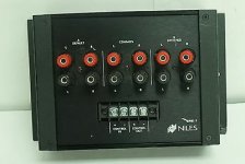
Attempting to build the equivalent of a Niles SPK-1 that uses a 5VDC trigger instead of 12V. Basically, I want to use a switched USB port on a TV to control it.
It's obvious that I need a relays for the positive lines, but do I also need to switch the grounds? Or can they all be commoned together?
Or does someone already make a box like this that I'm not aware of?
It's obvious that I need a relays for the positive lines, but do I also need to switch the grounds? Or can they all be commoned together?
Or does someone already make a box like this that I'm not aware of?
Attachments
Hi,
I would use a dual pole relay and switch plus and minus together. With 'regular' amp there won't be many issues i can think of atm with the use of a single pole relay (only switch the positive) but if you use a btl configured amp i could see some potential problems arising ( but i may be wrong too). Other members may chime in and confirm.
Could you be more accurate about the use you plan?
As there is little cost difference between a two pole and a four pole relay and there is a significant cost to repair a damaged amplifier, you might want to use a four pole relay.
I would use a 12 or 24 volt DC relay and a darlington transistor (TIP140) to switch it. Power from a wall wart. Only other part would be a 10K input resistor. The transistor has a reverse diode built in and should not require a heatsink.
I would use a 12 or 24 volt DC relay and a darlington transistor (TIP140) to switch it. Power from a wall wart. Only other part would be a 10K input resistor. The transistor has a reverse diode built in and should not require a heatsink.
Agree with Simon7000 about the diode on the relay's coil, protect your psu from kickback current.
Some food for thoughts ( give a general idea of configuration but without the darlington transistor, and there is confirmation BTL will be an issue so go for 4pole):
https://sound-au.com/absw.htm
Some food for thoughts ( give a general idea of configuration but without the darlington transistor, and there is confirmation BTL will be an issue so go for 4pole):
https://sound-au.com/absw.htm
Last edited:
If it is just USB powered, not software control over USB, you can get a little dongle DC-DC converter and get 12V for a relay off the USB. Real easy. No need for a wall wort.
True, good relays are not cheap.
True, good relays are not cheap.
I built a 6 in / 4 out speaker switch using 10 relays.
For a simple A or B switch using a 5V switched source, you only need one relay.
Use one of these --> https://www.digikey.ca/en/products/detail/carlo-gavazzi-inc/RRM004D5V/9520384
You can get a socket, too.

For a simple A or B switch using a 5V switched source, you only need one relay.
Use one of these --> https://www.digikey.ca/en/products/detail/carlo-gavazzi-inc/RRM004D5V/9520384
You can get a socket, too.
Has everyone forgotten about the single most popular power amp on this website, the Amp Camp Amp?? Its loudspeaker output binding posts are SPKR+(red) and SPKR-(black). SPKR+(red) is connected to ground. SPKR-(black) is driven by the amplifier's output transistors. Nelson Pass designed it that way and thousands of diyAudio members built it that way.
It would be very easy to destroy an Amp Camp Amp by only switching the red (+) terminals and tying the black (-) terminals together as a "common".
It would be very easy to destroy an Amp Camp Amp by only switching the red (+) terminals and tying the black (-) terminals together as a "common".
Not everyone... I suggested a 4PDT relay - I have a Yorkville with outputs that float WRT to ground and each other - 4 wire switching is required.
I built one using 40A Bosch type automotive relays and a 12V/5V server supply. Higher current capability lends to lower contact resistances. I used a 2P/6T switch so 5V ran LED indication, and 12V ran the relays.
You may also want to consider a boucherot on the input before the switch to keep the amp loaded, as well as avalanche devices across the outputs in the case that the stored charge in the coils becomes prone to arc while switching under load.
While i did not switch the common, it would be simple to add. The project is posted in a couple places on this forum under "Wolfy's Speaker Switch".
- Home
- Loudspeakers
- Multi-Way
- Trying to build a speaker level A/B switch