Hey guys,
I recently got a soundcraft EFX8 mixer in for general servicing. All the faders were in pretty bad condition so almost all the channels were scratchy and noisy. Replaced them all and all the channels are working fine except for one.
So the channel in question produces a high frequency hiss, its not consistent and changes in range. So here are things I have done so far,
1. Replaced the gain pot(P500A).
2. Jumped the connection on the "insert".
3. Replaced the quad op amp IC500A.
None of the above rectified the problem. Before replacing the opamp I did scope around and here is what I found- I can clearly see the trace jumping around at pin 1 of IC500. I checked pin 2 and pin 3 and I did not measure any anomalies there. I have done other troubleshooting things like measuring the voltage rails, looking for dired joints, checking for proper ground connections and tap test. I have also compared measurements against a working channel but can't see anything obviously wrong.
One other thing I would add is while I had the op amp desoldered and out of the circuit I did scope around pin 2 and pin3 pads while I was running a 1khz test tone. The DC offset at pin 3 was 2V higher than pin 2. I am not sure if that's significant or not.
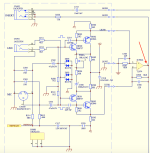
I was hoping you could give me some other things to look for. I have attached a pdf of the schematic of the input section.
Thanks
I recently got a soundcraft EFX8 mixer in for general servicing. All the faders were in pretty bad condition so almost all the channels were scratchy and noisy. Replaced them all and all the channels are working fine except for one.
So the channel in question produces a high frequency hiss, its not consistent and changes in range. So here are things I have done so far,
1. Replaced the gain pot(P500A).
2. Jumped the connection on the "insert".
3. Replaced the quad op amp IC500A.
None of the above rectified the problem. Before replacing the opamp I did scope around and here is what I found- I can clearly see the trace jumping around at pin 1 of IC500. I checked pin 2 and pin 3 and I did not measure any anomalies there. I have done other troubleshooting things like measuring the voltage rails, looking for dired joints, checking for proper ground connections and tap test. I have also compared measurements against a working channel but can't see anything obviously wrong.
One other thing I would add is while I had the op amp desoldered and out of the circuit I did scope around pin 2 and pin3 pads while I was running a 1khz test tone. The DC offset at pin 3 was 2V higher than pin 2. I am not sure if that's significant or not.
I was hoping you could give me some other things to look for. I have attached a pdf of the schematic of the input section.
Thanks
Attachments

Thanks, I shall check that. I'm trying to figure out how the circuit works. Can you please explain how a faulty C500 could cause that kind of noise. Also any pointers on how the circuit works would be greatly appreciated 🙂
TR500 / TR501 don't have backwards diodes protecting them so they might have had their EB junctions reverse-biased at some point (this clobbers low-noise performance), alas the 2SB737 is an almost mythical device now, not sure what the best replacement is. The ZTX951 may not be pin-out compatible...
Thanks guys for the pointers, I shall check them once I get back into the shop. Will report back.
Meantime could you help me figure how the circuit is working, I've been looking at the screen for a while trying to get my head wrapped around the circuit. I can see the transistors are in a sort of differential amp type of config, what are the transistors here used for I ask this, because the op amp is in a differential configuration too. Sorry in advance for the noob question.
Meantime could you help me figure how the circuit is working, I've been looking at the screen for a while trying to get my head wrapped around the circuit. I can see the transistors are in a sort of differential amp type of config, what are the transistors here used for I ask this, because the op amp is in a differential configuration too. Sorry in advance for the noob question.
The circuit has an "instrumentation amplifier" architecture arrangement. See https://en.wikipedia.org/wiki/Instrumentation_amplifier.
So I've taken some measurements. Checked against a working channel. I took measurements around the transistors and all the measurements which I took were identical. It was a bit hard to reach since the smd transistors were very close proximity to the input jacks. So I might have missed some measurements.
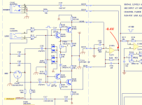
However I found one major variance - that is at pin 1 of IC100 (sorry in my first post I grabbed a screenshot of another channel). I measure -0.4V of offset. The test signal is also offset by that amount. All the other channels were way below that some were in the order of -0.02V the highest I measured in a good channel was -0.1V. I don't know if this is significant or not, what could be the fault that is causing this discrepency.
However I found one major variance - that is at pin 1 of IC100 (sorry in my first post I grabbed a screenshot of another channel). I measure -0.4V of offset. The test signal is also offset by that amount. All the other channels were way below that some were in the order of -0.02V the highest I measured in a good channel was -0.1V. I don't know if this is significant or not, what could be the fault that is causing this discrepency.
Attachments
That's partly because its drawn badly. Find a few microphone amp circuits and you'll find ones with the layout more logical. Its a hybrid mic preamp with CFP inputs.Meantime could you help me figure how the circuit is working, I've been looking at the screen for a while trying to get my head wrapped around the circuit. I can see the transistors are in a sort of differential amp type of config, what are the transistors here used for I ask this, because the op amp is in a differential configuration too. Sorry in advance for the noob question.
The inputs are DC coupled at the line inputs--- very surprising. Try your injected signal test on a working channel; you will likely get similar voltage readings.
Assuming the bias readings look good, let's return to your original noise complaint. Does hiss grow with advancing gain at P500A? There should be only modest shift in voltage at pin 1 of IC100 as you adjust gain. Try installing shorts at mike input connector and repeat hiss experiments with gain pot. What do you observe?
Assuming the bias readings look good, let's return to your original noise complaint. Does hiss grow with advancing gain at P500A? There should be only modest shift in voltage at pin 1 of IC100 as you adjust gain. Try installing shorts at mike input connector and repeat hiss experiments with gain pot. What do you observe?
The DC voltage readings at pin 1 was without the the input signal, I have set the gain knobs and all the other parameters identical (maybe an EQ pot might have been a bit out but gains were set the same).The inputs are DC coupled at the line inputs--- very surprising. Try your injected signal test on a working channel; you will likely get similar voltage readings.
Assuming the bias readings look good, let's return to your original noise complaint. Does hiss grow with advancing gain at P500A? There should be only modest shift in voltage at pin 1 of IC100 as you adjust gain. Try installing shorts at mike input connector and repeat hiss experiments with gain pot. What do you observe?
The hiss seem to grow with increase in gain. The hiss is not consistent and there is slight pop/click sounds too. I'll try to take a video of it. The voltage at pin1 doesn't show a huge change when adjusting the gain knob.
Could you please eleborate on the procedure you suggested with shorting pins on the mic input - short pin 2 to ground and pin 3 to ground? together or one at a time? what should I look for and what could I deduce from the result?
Thanks again
Yes, short pins 2 and 3 to ground. Maybe do the same to a good channel so you have a good reference for comparison.
Erratic pot behavior may be due to wear--- cleaning or replacement may help.
Compare hiss with the reference channel, both at max and minimum gains. This will help localize the fault. There are a couple simple tests of the opamp if it's unduly suspicious.
Erratic pot behavior may be due to wear--- cleaning or replacement may help.
Compare hiss with the reference channel, both at max and minimum gains. This will help localize the fault. There are a couple simple tests of the opamp if it's unduly suspicious.
Thanks I shall try that, but I wanted to ask what is the purpose of shorting the input pins to ground?Yes, short pins 2 and 3 to ground. Maybe do the same to a good channel so you have a good reference for comparison.
Erratic pot behavior may be due to wear--- cleaning or replacement may help.
Compare hiss with the reference channel, both at max and minimum gains. This will help localize the fault. There are a couple simple tests of the opamp if it's unduly suspicious.
I did change the pot very early on. It didn't help with the noise. The popping sound doesn't correlate to the movement of the gain knob.
I also did change the op amp. What kind of tests could I do to check the op amp? For future reference as well.
Thanks
Shorting the inputs just helps reduce a few uncertainties. There is a notion of assessing noise with a shorted input which can measure voltage noise and an open connection assesses current noise. But this device has its inputs biased by 1.2k resistors (R109 and R110), a relatively low value, so not much to be learned.
Thanks for emphasizing that pops are immune to gain position. The defect could be almost anything. Try tapping, pressing gently, prying, etc, to reveal a possible intermittent connection.
I think we can do some sub-circuit isolation to help find the defect, but I need to know -V1 and +V2 rail supply voltages that don't seem to shown. Would you advise what you measure?
How are boards interconnected? Are there jumper wires?
Thanks.
Thanks,
The voltages are +/-15V (though I need to double check this). Its +/-15V for the opamps.
The input board and the rest of is connected via jumper wires.
I've been doing some tap testing and it doesn't effect the noise.
The voltages are +/-15V (though I need to double check this). Its +/-15V for the opamps.
The input board and the rest of is connected via jumper wires.
I've been doing some tap testing and it doesn't effect the noise.
The easiest first test is to disconnect one end each of jumpers LK100 and LK101. Obviously, this isolates the opamp stage from the input stages. You should find 0V at the opamp output and it should be free of noise and pops.
Assuming all is well, we will next try to test each half of the input section separately to attempt to localize the problem. I have to think about how to do this with minimal fuss.
Let me know about the first test and I'll think about next experiment.
Thanks.
Assuming all is well, we will next try to test each half of the input section separately to attempt to localize the problem. I have to think about how to do this with minimal fuss.
Let me know about the first test and I'll think about next experiment.
Thanks.
The easiest first test is to disconnect one end each of jumpers LK100 and LK101. Obviously, this isolates the opamp stage from the input stages. You should find 0V at the opamp output and it should be free of noise and pops.
Thanks, sounds like a good idea. I'll do that and see.
I have done something similar along that line, that is to connect an open TRS jack into the insert. It cuts out the sound completely obviously, and I did measure the hiss/pop on the send pin of the jack.
Guys some updates -
Some findings:
1)Collector of TR100/101 and base of TR102/103 measures at -10.01V on the noisy channel. All the other channels at the same point measures at -9.96 to -9.98V. Gain knob or injecting a signal or not didn't have any effect. Again I'm not sure if this is significant.
2)I placed the scope at base of TR100 and I didn't see the hiss/pop noise there. However at the collector of that transistor and base of TR102 I sort of saw the noise signal but it was very hard to see and not as significant as seen from the output of the opamp.
3)Placing the probe at base of TR102 produces a noise that the same on all channels. But on the bad channel the hiss/pop sounds seem to get louder if I tap that point from the tip of the probe.
4)Maybe a pointless point but - I measured varying of voltage (millivolts) at the negative lead of C115 with respect to ground. This wasn't the case for the good channels. I did add a cap parallel to it and it didn't do anything with the noise. Besides, signal going to the "insert" jack has noise on it.
I have a small video clip of the noise, here is the link:
The owner of the mixer has got a gig coming up in couple of days, he is ok sacrificing one channel. But I would like to identify the fault for future reference too. Hopefully I get to diagnose the problem with your guys help.
Thanks for the help again.

I wasn't able to do this, but will be doing this soon.The easiest first test is to disconnect one end each of jumpers LK100 and LK101. Obviously, this isolates the opamp stage from the input stages. You should find 0V at the opamp output and it should be free of noise and pops.
Some findings:
1)Collector of TR100/101 and base of TR102/103 measures at -10.01V on the noisy channel. All the other channels at the same point measures at -9.96 to -9.98V. Gain knob or injecting a signal or not didn't have any effect. Again I'm not sure if this is significant.
2)I placed the scope at base of TR100 and I didn't see the hiss/pop noise there. However at the collector of that transistor and base of TR102 I sort of saw the noise signal but it was very hard to see and not as significant as seen from the output of the opamp.
3)Placing the probe at base of TR102 produces a noise that the same on all channels. But on the bad channel the hiss/pop sounds seem to get louder if I tap that point from the tip of the probe.
4)Maybe a pointless point but - I measured varying of voltage (millivolts) at the negative lead of C115 with respect to ground. This wasn't the case for the good channels. I did add a cap parallel to it and it didn't do anything with the noise. Besides, signal going to the "insert" jack has noise on it.
I have a small video clip of the noise, here is the link:
The owner of the mixer has got a gig coming up in couple of days, he is ok sacrificing one channel. But I would like to identify the fault for future reference too. Hopefully I get to diagnose the problem with your guys help.
Thanks for the help again.
Attachments
Hi Yambo,
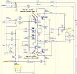
If you open the wire jumpers at LK100 and LK101, the nominal voltage drops across R106 and R103 should be about 0.864V. There is some coupling between the two input stages, so set the gain pot at 0 to minimize transfer of noise error from a defective input stage into its opposite twin. Try monitoring the voltages at the open LK100 and LK101 terminals--- you might be lucky to spot the misbehaving path with your scope. I'm assuming the defect lies within one of the two input paths
If the noise is too subtle to spot with with the scope, you can implement the troubleshooting aid in the attached pic. The added resistor mimics the gain provided by the opamp stage; the added 10uF cap and floating wire will allow you to probe LK100 and LK101 individually, or other points of interest, eg. grounds, -15V rail, or even +15V if you swap 10uF polarity.
Good luck.
- Home
- Amplifiers
- Solid State
- Troubleshooting noise at preamp section of a mixer (Soundcraft EFX8)