I am having a big issue with the solid state guitar amp i built. The pre amplifier is from the dean markley k-20x and the power amp is the TDA2040 30W amplifier. I am reading 15.5 to 16 volts dc on the positive speaker output and -15.5 to -16 volts dc on the negative speaker output (those are my power supply voltages).
I have desoldered the jumper wire that connects the pre amplifier and power amplifier so i know the issue is there. I have also checked every single resistor and capacitor in the power amplifier and checked my board design again.
I noticed only the positive side TDA2040 appears to short and heat up and when i switched it for a new one and turned the amp on i was able to see the voltage quickly rise to those 15.5 volts on the oscilloscope(then it just stays on that value). Also when i desolder the shorted TDA only pins 4 and 5 (output and V+) check for continuity(these pins measure about 30M ohm on a brand new chip), and the rest of the pins seem okay. The negative side TDA2040 seems okay too.
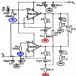
I attached the power amp schematic below.
Id love to hear your opinion on this. This is for a final year project and im getting desperate.
I start to regret not having done a little arduino toy like the rest of the class instead of a real eletronics project.
P.S- I did not put any isolation between the chips and the heatsinks because I didnt think that would be a problem. Please tell me if it is. The two heatsinks are separate from each other and arent touching anything else.
Double P.S- Im using a 12-0-12V 80VA transformer with a BR356L rectifier and two 2200uF/25V capacitors as my power supply
I have desoldered the jumper wire that connects the pre amplifier and power amplifier so i know the issue is there. I have also checked every single resistor and capacitor in the power amplifier and checked my board design again.
I noticed only the positive side TDA2040 appears to short and heat up and when i switched it for a new one and turned the amp on i was able to see the voltage quickly rise to those 15.5 volts on the oscilloscope(then it just stays on that value). Also when i desolder the shorted TDA only pins 4 and 5 (output and V+) check for continuity(these pins measure about 30M ohm on a brand new chip), and the rest of the pins seem okay. The negative side TDA2040 seems okay too.
I attached the power amp schematic below.
Id love to hear your opinion on this. This is for a final year project and im getting desperate.
I start to regret not having done a little arduino toy like the rest of the class instead of a real eletronics project.
P.S- I did not put any isolation between the chips and the heatsinks because I didnt think that would be a problem. Please tell me if it is. The two heatsinks are separate from each other and arent touching anything else.
Double P.S- Im using a 12-0-12V 80VA transformer with a BR356L rectifier and two 2200uF/25V capacitors as my power supply
Attachments
You need to begin somewhere and so...
1/ Use a bulb tester. A chip amp draws minimal current normally and so a bulb tester with a low wattage bulb of 40 watts or less could save you damaging any chips. Try a fridge bulb.
2/ Layout can be of extreme importance on designs like this. How is it built? PCB or stripboard etc.
3/ Use an oscilloscope to see if it is unstable.
4/ Assuming it is not oscillating then voltage checks should reveal any problems. Remember it is really a basic opamp circuit and so will follow all the rules.
No, it is correct but missing from the schematic and would cause such a problem.
Perhaps post some photos of your build.
Perhaps post some photos of your build.
1/ A good careful visual inspection of the circuit for shorts, cold joints etc.
2/ Check all components for value.
3/ Check layout against original circuit design.
In my experience power rail voltages on output usually mean IC is blown or a serious mistake in circuit somewhere.
2/ Check all components for value.
3/ Check layout against original circuit design.
In my experience power rail voltages on output usually mean IC is blown or a serious mistake in circuit somewhere.
Before the grounding conversation gets out of hand: If you connect all grounds in the circuit together and connect them to the centre point (0 V) in your ±15 V supply, the circuit should work. If you want better performance, I suggest keeping the power ground (circled in grey), feedback ground (circled in red), and input ground (blue) separate.
Since this is a balanced amp, I would use the centre point between the two 100 uF bypass caps as the ground reference. Then take the input grounds through separate traces (or a copper pour) to this reference. Do the same for the feedback ground.
But you're not there yet. You need to get the amp working before you can start to worry about performance.
Once you've followed the previous recommendations: Verified that the amp is indeed built as per the schematic, checked for cold solder joints, etc., remove R7. This will allow you to test each amp half separately.
With R7 removed, you should be able to run a signal into the amp and get a clean output on the (+) amp. You can then connect a signal to the non-inverting input of the (-) amp. That should get a clean output on it. If not, you'll know which amp half to go debug.
Once you have both amp halves working, put R7 back in place.
Don't worry about the script kiddies and their Arduinos. If a project isn't challenging it is not work undertaking. Just saying. (And, yes, software can be challenging too).
Tom
Attachments
Last edited:
- Home
- Amplifiers
- Chip Amps
- Troubleshooting my 30W solid state amp