I don't have a spare computer PSU, I've been meaning to get one for this kind of thing. It's possible that it's got a poor connection somewhere, I can examine the cable run from the battery and make sure it's not failing somewhere. That line does power my properly-working amp reliably, however. I have one 30A fuse installed out of two total. I tried 10A fuses as you suggested and they all popped when I connected B+.
If you ask around at computer repair shops, you can likely get several supplies for very little.
Did it blow the 10 amp fuse with no remote voltage?
Did it blow violently or did it open cleanly (little or no soot in the area where the fusible element oened)?
Did it blow the 10 amp fuse with no remote voltage?
Did it blow violently or did it open cleanly (little or no soot in the area where the fusible element oened)?
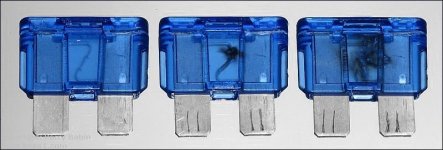
Yes, the 10A fuses blew with the ignition off, when attempting to connect the battery cable. It seemed violent and there's a small amount of soot visible inside the fuse housing. I've included a photo because I don't have a good sense of how that looks.

This is both sides of the same fuse.
This is both sides of the same fuse.
It generally looks like the fuse on the left when the current is very high.
Try installing a higher current fuse, like the 30A and then quickly replacing it with the 10A. The charging caps may have blown the 10A (a 15A is what is more commonly used). If these aren't name brand fuses (Bussmann, Littelfuse), they may not function as expected.
Make sure that there is no remote voltage when you do this.
Does the lower rated fuse (10 or 15A) hold with no remote voltage.
Attachments
Tested in the truck again; connected B+ and ground with a single 15A fuse and it held steady at +12V across the terminals. I connected the remote and powered the amp and it played briefly, intermittently as before, and then the fuse popped. The voltage across the terminals stayed steady the whole time, with no cycling, but it dropped to +11V after the fuse blew.
The voltage should not have remained low (11v) after the fuse blew unless the battery is weak, you have a bad connection or something else is dragging it down.
It's pulling excessive current.
There are 6 output pairs. Each pair has a small transistor between the two output transistors. For each of the 6 pairs, you need to measure the DC voltage between the two emitter legs of the outputs in each pair. Be aware that the voltage will likely be well below 1v. Check all 6 pairs. It's likely that one pair will have a reading that's higher than the rest.
It's not good relying on the amp's over-current protection but if it's been OK until now, it may survive. If you had an inline current limiter (large 2 ohm resistor, old incandescent headlamp... it would be a bit less risky.
The battery is new and there are no other sources of amp drain that I'm aware of; the truck wrecked batteries when I got it because of a hacky ignition fix but returning it to stock sorted that.
There is a splice in the B+ cable that I don't entirely trust and I'll check that before proceeding with further diagnostics; I forgot it was there and I'm going to feel pretty foolish if it was the problem all along.
Barring that I'll track down a computer PSU and test those transistors on the bench. I've needed to build a current limiter for this kind of work anyway.
You can use something like a length of small (16g, 18g) wire as a current. You wouldn't leave it unattended (because it can overheat and possibly burn) but it can be used if you don't have anything better.
After some finagling I got a power supply set up and got the following values on the emitter legs of the D718/B688 pairs:
Pair 1: 0V silent, 0.3mV playing
Pair 2: 0.3mV silent, 1.3V playing
Pair 3: 0V silent, 0.2mV playing
Pair 4: 0V silent, 0.2mV playing
Pair 5: 0V silent, 27mV playing
Pair 6: 0V silent, 33mV playing
Here's the order I tested them:

Pair 1: 0V silent, 0.3mV playing
Pair 2: 0.3mV silent, 1.3V playing
Pair 3: 0V silent, 0.2mV playing
Pair 4: 0V silent, 0.2mV playing
Pair 5: 0V silent, 27mV playing
Pair 6: 0V silent, 33mV playing
Here's the order I tested them:
With no power applied, measure the resistance between the emitter legs of each pair. Is the reading for pair 2 higher?
Note that the readings are going to be at the lower limit of your meter so measure carefully.
Look at the solder connections on the terminals of all of the large white ceramic resistors. Move the resistors to see if there any cracks.
If you resolder their connections, add new solder, desolder then resolder.
I registered 0.2 ohm across the emitter legs of pair 2 and 0 ohm on all the rest. I reckon I'm at the limit of what my meter can measure. The ceramic resistors feel solid enough but the solder on 1 and 2 look a little lifted off the pads around the perimeter, like it wasn't laid down perfectly.
If you move the body of those 2 resistors, can you see movement in the solder?
Can you resolder them?
Can you resolder them?
Remove the resistor from the channel that read higher and one from another channel that read low and check them out of the circuit. Read outside leg to outside leg as well as from center leg to each outside leg.
Resistor 2 (the channel that read higher): 0.2ohm across outside legs, 0ohm left leg to centre, 0ohm centre to right leg
Resistor 1: 0ohm across outside legs, 0ohm left leg to centre, 0ohm centre to right leg.
Left to right is based on measuring from the side with the spec printed on it.
Resistor 1: 0ohm across outside legs, 0ohm left leg to centre, 0ohm centre to right leg.
Left to right is based on measuring from the side with the spec printed on it.
For reference, the attached image is likely what's inside the ceramic.
Do you have any 12v incandescent bulbs on hand? Something like a dome light or brake lamp would be usable. I'd like to see the resistors with a bit more current through them and without a variable 12v supply, you need some other sort of limiting device.
Do you have any 12v incandescent bulbs on hand? Something like a dome light or brake lamp would be usable. I'd like to see the resistors with a bit more current through them and without a variable 12v supply, you need some other sort of limiting device.
Attachments

I have a handful of bulbs from the truck I replaced with LEDs. How should I connect the bulb(s) and resistor network?
One bulb terminal to the 12v supply. The other to one outer terminal of the resistor. The other outer terminal of the resistor to ground.
If you have something like an 1156 bulb (running lights), that should work.
Set it up and connect the meter to the outer terminals of the resistor. Then apply power just long enough to get a meter reading.
What is the DC voltage across each resistor when power is applied.
If you have something like an 1156 bulb (running lights), that should work.
Set it up and connect the meter to the outer terminals of the resistor. Then apply power just long enough to get a meter reading.
What is the DC voltage across each resistor when power is applied.
I got 185mVDC across the outer terminals on the resistor from the channel that read high. The other resistor I removed measured 174mVDC across the outer terminals.
I don't think that (5%) would make a difference.
When you reinstall the resistors, swap their positions to see if the higher voltage drop across the resistors follows the resistor or remains with the same channel.
When you reinstall the resistors, swap their positions to see if the higher voltage drop across the resistors follows the resistor or remains with the same channel.
- Home
- General Interest
- Car Audio
- Troubleshooting an Alpine MRV-F352