Hi everyone,
It's my first post here, and I'm turning over to this community because I have exhausted all other options.
Recently, I purchased a few Eurorack PSU kits from Erica Synths, hoping that I would get a well designed and reliable product. Yet, I'm having a lot of trouble with theses PSU.
I should also mention that I'm just an amateur in electronics and still learning, but I have some basic electronic knowledge, have assembled quite a few synth and pedal kits, can read a schematic, have some decent equipment (digital oscilloscope, pro multimeter, good quality soldering iron, and a wide variety of components...). Not entirely a n00b but still...
I also want to mention, I followed meticulously all the instructions on the Assembly Guide provided by the manufacturer, checking and double checking component polarities and values at every step.
After assembling it, when came the time to test it, the fuse (F1) blew up instantly. So my initial thought was that something was shorted. But I couldn't find anything wrong with my assembly job and nothing appeared to but damaged, so I changed the fuse with another one of a slightly higher rating (from 1A to 1,5A) and proceeded to another test. And this time the fuse hold still but the transformer would get very hot really fast (I couldn't let it plugged in more than a few minutes without risking to burn something), and my ammeter would read around 1,2A without any load connected to it.
So I disconnected the transformer from the rest of the board and tested it, no problem here (the secondary was outputting 12V AC between the center point and each end of the coil). Same for the diode bridges, it worked as expected.
After a few unsuccessful attempts to diagnose it, I asked a friend of mine to take a look at it, and we were able to determine that this issue would not occur if the circuit only has one Full Bridge Rectifier instead of two as its designed to (I also read online that this type of design could cause some issues).
Great, now my PSU was working correctly, or so I thought...
Testing on my multimeter the positive output would give me around +12V and the negative output would give around -12V. But when I took a look at the negative output current on my oscilloscope, I noticed something very wrong. The current is oscillating between -9V and -16V with a ramp/sawtooth waveform at 250Hz. And after spending hours scratching my head, I can't figure out why.
I also tried assembling another kit with the single bridge rectifier modification, thinking that I may have damaged something. And the exact same issue appeared: same ramp waveform -9V to -16V oscillation at 250Hz, except this time no fuse blew up, the transformer did not overheat, and no ridiculous ampere reading.
I really don't know how to fix this and I would appreciate any help, advice or suggestions here.
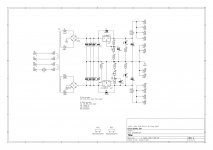
Here is the original schematic:

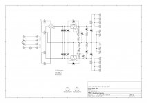
Here is the schematic with the single full bridge rectifier modification (and without the unused parts):

Here is a picture of the negative output on my oscilloscope:

Here is a picture of the PSU itself:

And for more details, here is a link of the product page on the Erica Synths website
It's my first post here, and I'm turning over to this community because I have exhausted all other options.
Recently, I purchased a few Eurorack PSU kits from Erica Synths, hoping that I would get a well designed and reliable product. Yet, I'm having a lot of trouble with theses PSU.
I should also mention that I'm just an amateur in electronics and still learning, but I have some basic electronic knowledge, have assembled quite a few synth and pedal kits, can read a schematic, have some decent equipment (digital oscilloscope, pro multimeter, good quality soldering iron, and a wide variety of components...). Not entirely a n00b but still...
I also want to mention, I followed meticulously all the instructions on the Assembly Guide provided by the manufacturer, checking and double checking component polarities and values at every step.
After assembling it, when came the time to test it, the fuse (F1) blew up instantly. So my initial thought was that something was shorted. But I couldn't find anything wrong with my assembly job and nothing appeared to but damaged, so I changed the fuse with another one of a slightly higher rating (from 1A to 1,5A) and proceeded to another test. And this time the fuse hold still but the transformer would get very hot really fast (I couldn't let it plugged in more than a few minutes without risking to burn something), and my ammeter would read around 1,2A without any load connected to it.
So I disconnected the transformer from the rest of the board and tested it, no problem here (the secondary was outputting 12V AC between the center point and each end of the coil). Same for the diode bridges, it worked as expected.
After a few unsuccessful attempts to diagnose it, I asked a friend of mine to take a look at it, and we were able to determine that this issue would not occur if the circuit only has one Full Bridge Rectifier instead of two as its designed to (I also read online that this type of design could cause some issues).
Great, now my PSU was working correctly, or so I thought...
Testing on my multimeter the positive output would give me around +12V and the negative output would give around -12V. But when I took a look at the negative output current on my oscilloscope, I noticed something very wrong. The current is oscillating between -9V and -16V with a ramp/sawtooth waveform at 250Hz. And after spending hours scratching my head, I can't figure out why.
I also tried assembling another kit with the single bridge rectifier modification, thinking that I may have damaged something. And the exact same issue appeared: same ramp waveform -9V to -16V oscillation at 250Hz, except this time no fuse blew up, the transformer did not overheat, and no ridiculous ampere reading.
I really don't know how to fix this and I would appreciate any help, advice or suggestions here.
Here is the original schematic:
Here is the schematic with the single full bridge rectifier modification (and without the unused parts):
Here is a picture of the negative output on my oscilloscope:
Here is a picture of the PSU itself:
And for more details, here is a link of the product page on the Erica Synths website
Attachments
-
 2019-02-12 17.13.14.jpg1,002.5 KB · Views: 680
 -
 2019-02-12 17.13.27.jpg815.3 KB · Views: 482
 -
erica_synths_diy_psu_schematics.pdf41.4 KB · Views: 93
-
 erica_synths_diy_psu_schematics.jpg179.1 KB · Views: 1,228
 -
 erica_synths_diy_psu_schematics MOD.jpg173.7 KB · Views: 603
 -
erica_synths_diy_psu_schematics MOD.pdf268.3 KB · Views: 81
Last edited:
I would remove C8.
Okay. Should I simply remove it or should I also bridge also this connection?
Also, can you elaborate on this suggestion?
Okay. Should I simply remove it or should I also bridge also this connection?
The capacitor C8 is in the wrong place. It should be in parallel with R6 and R8,
with the positive lead to ground. This may not be the whole problem, though.
First I agree, no C8 at all.
R5 is missing, sets the max current.Data says 15k devided by max current, so for 3A 15/3= 5k.
Are the coolers isolated, if not the regulator IC be mounted with isolation.
If the (one off) fuse blows there is
- a bad electrolytic
- a bad diode
- a reversed diode
- a short circuit (to much solder ?)
The circuit with one bridge has a connection missing.J7 AND J17 to Gnd !
Mona
C8 has a wrong value. In the datasheet it is an option (loop lead compensation) with a value of 50nF, not 4.7uF which is likely to make the regulator oscillate.
Worse, on the schematic with only one bridge rectifier: one secondary winding is wrongly connected. This flaw may not have been implemented in practice.
Worse, on the schematic with only one bridge rectifier: one secondary winding is wrongly connected. This flaw may not have been implemented in practice.
I will try this mod, and let you know what happens.The capacitor C8 is in the wrong place. It should be in parallel with R6 and R8, with the positive lead to ground.
This seems to be the general opinion. I will try it first.First I agree, no C8 at all.
The manufacturer mentioned on the schematic that it should not be connected for this version of the circuit. But I guess it is worth trying too.R5 is missing
No, they are not. I also took the liberty of applying some thermal paste on them, and it might be a conductive one. 🙁Are the coolers isolated, if not the regulator IC be mounted with isolation.
Interesting. So you think there should be a capacitor at C8, but with a lower value. Is there a specific type of capacitor I should use (ceramic, mylar, tantalum,...)?C8 has a wrong value. In the datasheet, it is an option (loop lead compensation) with a value of 50nF, not 4.7uF which is likely to make the regulator oscillate.
You are right. I noted that 0V is connected to the bridge, and 12V to ground. But in practice, it's the other way around. I just misread the schematic. My bad.Worse, on the schematic with only one bridge rectifier: one secondary winding is wrongly connected. This flaw may not have been implemented in practice.
Last edited:
Interesting. So you think there should be a capacitor at C8, but with a lower rating. Any kind of capacitor I should use (ceramic, mylar, tantalium,...) ?
Page 16 of the datasheet, second schematic, text below. Probably a film capacitor just to be sure.
Really? How so?
Lower secondary winding. Should form a center-tap with the upper secondary winding. As shown, the lower secondary winding will short-circuit through the lower left rectifier diode during one half period.
The modified schematic seems to show J17, J20 shorted across part of the rectifier. (very bad!)
This should be dead simple:
J7+J17 = ground.
J3= rectifier AC#1
J20= rectifier AC#2
Rectifier + and - should have NO connection to the transformer!!!
Be sure the rectifier has not been damaged!
This should be dead simple:
J7+J17 = ground.
J3= rectifier AC#1
J20= rectifier AC#2
Rectifier + and - should have NO connection to the transformer!!!
Be sure the rectifier has not been damaged!
Last edited:
I removed C8 as suggested above, and it worked !😀
No more sawtooth, just a nice and flat -12V.
Thank you so much everyone, all your answers have been very helpful.
No more sawtooth, just a nice and flat -12V.
Thank you so much everyone, all your answers have been very helpful.
The modified schematic seems to show J17, J20 shorted across part of the rectifier. (very bad!)
This should be dead simple:
J7+J17 = ground.
J3= rectifier AC#1
J20= rectifier AC#2
Rectifier + and - should have NO connection to the transformer!!!
Be sure the rectifier has not been damaged!
I know, as I admitted to FauxFrench earlier I made a mistake on my schematic. Actually, my transformer has only one center tap wire and it’s connected to J7 which provides the ground, and on the positive half of the board I cutted this trace and wired the negative output of the bridge to the negative part of the circuit. So it’s all good.
- Status
- Not open for further replies.
- Home
- Amplifiers
- Power Supplies
- Troubles with Eurorack Bipolar Linear Power Supply DIY Kit