Thank you unclejed613, unfortunately, I am not technically savvy enough to fully benefit from your detailed guidance. However, I looked at the unit to try and follow you. This is a dual-mono design and (besides the large toroidal transformer and large power caps) the only significant board they share in common is the "Protector Unit" (as named by Denon's schematic). This board looks like it would be easy to remove and work on. Fortunately, I just so happen to have another POA2800 that is fully functional, so I can try to narrow the problem on a larger scale first. Do you think the DC correction & capacitance multiplier circuitry are included on this one board? Also, I know anything is possible, but did you think this might be a good approach, or would I stand a significant chance of damaging my good Protection-Unit board by plugging it in the bad system? Thanks again !!
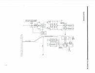
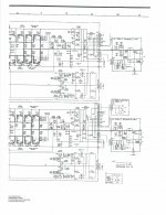
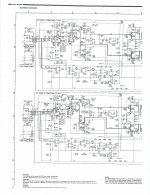
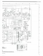
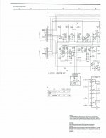
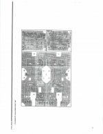
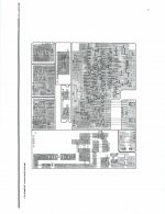
It was too tempting, so I went ahead and swapped the board, but unfortunately, still got the same high DC offset. I attached the schematic in case your interested in having a look at any of it, but I wouldn't know if any of the other misc parts the two channels have in common could cause this result.
Attachments
-
 2011_12_29_01_58_22 1.jpg158.8 KB · Views: 302
 -
 2011_12_29_01_58_22 9.jpg327.4 KB · Views: 220
 -
 2011_12_29_01_58_22 8.jpg383.3 KB · Views: 208
 -
 2011_12_29_01_58_22 7.jpg313.2 KB · Views: 183
 -
 2011_12_29_01_58_22 6.jpg229.2 KB · Views: 210
 -
 2011_12_29_01_58_22 5.jpg308.9 KB · Views: 269
 -
 2011_12_29_01_58_22 4.jpg352.5 KB · Views: 221
 -
 2011_12_29_01_58_22 3.jpg418.6 KB · Views: 221
 -
 2011_12_29_01_58_22 2.jpg503.5 KB · Views: 289
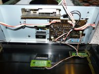
Oh, here are some pics of the amp. The first shows the board I swapped. Sorry about all the pics, just thought I would make it easy for anyone to dig as deep as they might want. Please let me know if anything else looks like a good candidate to easily swap. Thanks.
Attachments

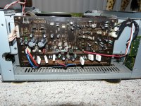
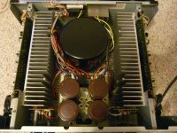
I woke up this morning and re-checked both channels. The DC offset strangely appears identical on both channels. They both start at about 6.4V then both climb to 6.97 after a minute. I wonder if both channels could possibly have the same issue that is causing identical DC offset? BTW, in the 1st pic (above), I only swapped that larger board.
the +/-72V rails might be switched off. these feed the diff amps and such for both channels. they are controlled by the REMOTE ON/OFF signal from TR203. check the DC remote jack. there's a plug with an intrtnal switch contact. if the contact is oxidized, it might turn off the +/-72V rails
unclejed613, you got it !!
I first swapped the tiny board that contains the DC remote jack and oddly it still did not work. Then I tried supplying 12v and then the DC offset dropped to a reasonable level (25mV and 60mV). Not perfect, but in the realm of functional. Even after I removed the 12V signal, the DC offset remained low. As you predicted, the contacts were oxidized. I think the reason it did not immediately work when I swaped the board is because both boards were oxidized, but never gave me an issue with the other POA2800.
Looking back, it turned out to be a minor problem....but knowing where to look...priceless. Thank you for taking the time to explain! These Denon units sound great and it would be a shame to trash one. I can check the bias next but I don't think that is going to get the DC offset any better? Maybe it's good enough?
glad i could be of help. 60mV is definitely much better than 5V. the bias is probably ok, and really wouldn't have much of an effect on offset. don't worry about 60mV of offset, as offset really doesn't become an issue until it gets over 100mV or so.
Well, just to follow up, I had thought this was fixed and let it sit a while. However, I pulled it out today and it's still not working right. It appears as if the DC offset is intermittently reading different values. Sometimes it's good, other times it goes back as high as 5V again. I looked at the DC input plug again but have determined that the plug is working correctly. Oddly, if I tap on the large power caps, the DC offset goes nuts. At first I thought this might be a cold solder joint or bad wire-wrap. Now I am thinking that the caps are bad. Has anyone ever seen bad caps have these symptoms when they go bad, or should I look further for bad solder joints? Anyhow, it looks like I would have to take absolutely everything apart to get to these caps. I might have to take this somewhere and have a pro look at this.
check all your grounds and ground traces (and any ground screws that tie the caps to the chassis from the board)before assuming it's the caps. a flaky ground going to the amp input can cause a lot of offset problems. a bad cap is more likely to cause hum in the output (if it's dried out or open). or overheating of the bridge rectifier (if it's leaky). the power amp stages are much like op amps, so if you had uneven rail voltages (such as +75 and -60), it still won't cause offset, as long as the input stage maintains it's ground reference.
the other thing that will cause offset, is the loss of the input stage rails, as i've already mentioned.
the other thing that will cause offset, is the loss of the input stage rails, as i've already mentioned.
Last edited:
Thanks again unclejed613, It took a good bit of digging, but it was a ground, as you suspected. This time it's rock solid!! Previously, it looked to be fixed but was not consistent and I excused that since I believed the DC input contact was still not perfectly clean. Now it works without fail.
Greatly appreciate your help !!
Greatly appreciate your help !!
Last edited:
Hi unclejed613,
Thanks for helping here. I'm still under the weather, so I'm sorry I haven't been around. I hope to be back soon.
-Chris
Thanks for helping here. I'm still under the weather, so I'm sorry I haven't been around. I hope to be back soon.
-Chris
Hi everyone, I hope someone might be able to help me with my amp. its not the poa-2800 but the poa-2400. ive read with interest how these amps are fixed but havent seen one with a similar fault as mine.
The right channel is faulty as it trips the protection as the volume is raised. I have ready comments here about this fault but what I cant figure out is why the input levels on the front of the amp are reversed! I purchased the amp in this condition and hoped to have it working but this has me stumped.
As you can see the levels are pointing to 10 and believe it or not but this is the lowest volume. im sure this isnt correct, but turning the dial clockwise increases the volume. Now every photo I have seen of this amp the dials are pointing straight up at 0 which makes me assume usually it is turned counterclockwise to increase the volume with max being 10.
Could anyone kindly explain to me why this is the case, if its normal in any way? or what fault could have caused this?
Thank you
The right channel is faulty as it trips the protection as the volume is raised. I have ready comments here about this fault but what I cant figure out is why the input levels on the front of the amp are reversed! I purchased the amp in this condition and hoped to have it working but this has me stumped.
An externally hosted image should be here but it was not working when we last tested it.
As you can see the levels are pointing to 10 and believe it or not but this is the lowest volume. im sure this isnt correct, but turning the dial clockwise increases the volume. Now every photo I have seen of this amp the dials are pointing straight up at 0 which makes me assume usually it is turned counterclockwise to increase the volume with max being 10.
Could anyone kindly explain to me why this is the case, if its normal in any way? or what fault could have caused this?
Thank you
apologies as I wasnt able to edit my original post, at the moment I dont have a pre-amp as yet so have been testing the power amp with a cd player connected to it. Im waiting for the denon pra-1200 to arrive (very soon) so im unsure how the power amp levels should be set if its to be controlled by the pre-amp. if the power amps input levels are set to 5 which in my case is louder than 10, would the pre-amp control the power amps volume correctly or is what im experiencing connecting directly a sign of a separate fault to the faulty right channel?
any help would be greatly appreciated.
thanks
any help would be greatly appreciated.
thanks
How to Fix POA-2800 Intermittent Problems
I acquired a POA-2800 almost 14 years ago. It exhibited the problems that you all describe to the point where both channels failed to operate with occasional (and increasingly LESS occasional) bursts of beautiful operation. Recently, with a lot of time on my hands due to COVID-19. I traced the problem down to the "protection" circuits. Not only do they protect against DC on the speaker terminals, they shut down the power supply to the pre-amp stages. I could not find the exact cause, but I bypassed the pass transistors that shut down the preamp power supply and it works beautifully. Because the speaker DC protection works fine, I decided that the preamp power supply shut down was not only not necessary, it was in fact a fatal flaw in the design of the amp. I strongly suggest that anyone struggling with this amplifier take the same action. Note: when bypassing the transistors I recommend removing them and isolating their circuits from power. The critical anti-DC speaker protection circuits should still work because you are controlling the devices that are inappropriately being shut down for the preamp circuits and not affecting the speaker protections. These circuits are unusual and not used in contemporary complimentary transistor output circuits.
I acquired a POA-2800 almost 14 years ago. It exhibited the problems that you all describe to the point where both channels failed to operate with occasional (and increasingly LESS occasional) bursts of beautiful operation. Recently, with a lot of time on my hands due to COVID-19. I traced the problem down to the "protection" circuits. Not only do they protect against DC on the speaker terminals, they shut down the power supply to the pre-amp stages. I could not find the exact cause, but I bypassed the pass transistors that shut down the preamp power supply and it works beautifully. Because the speaker DC protection works fine, I decided that the preamp power supply shut down was not only not necessary, it was in fact a fatal flaw in the design of the amp. I strongly suggest that anyone struggling with this amplifier take the same action. Note: when bypassing the transistors I recommend removing them and isolating their circuits from power. The critical anti-DC speaker protection circuits should still work because you are controlling the devices that are inappropriately being shut down for the preamp circuits and not affecting the speaker protections. These circuits are unusual and not used in contemporary complimentary transistor output circuits.
Hi Folks! Thanks Chris and Uncle Jed. Just had the same issue with a POA 2800. between 3 and 7 Volts on the speakers, both channels with the same offset. There is a tiny screw attaching the power supply psb at the rear. It's accessible after removing the bottom plate. It was removed, cleaned and reinstalled FIRMLY. All wonderfull now. Strange that the offset did not trigger the protection cct.

Hi Peter,
As equipment ages, we are starting to see all kinds of common to chassis connections failing. Something we didn't see when the stuff was new or "young". I am seeing rivets (still tight) holding ground lugs go high resistance. Using the chassis as a common ground is a poor idea for starters.
I haven't examined the circuit, but the offset didn't trigger protection because either the DC protection circuit didn't work due to the bad connection, or it "saw" no DC offset. Depends where it's reference comes from.
Not impressed with that design choice at all.
Hi sardobang,
I know this is an ancient post, but in case someone is reading later in time ...
I wouldn't change the way the circuit works. I have discovered over the years that with Yamaha especially, something that makes no sense as to why they did something actually has a reason. When that rears its ugly head, it typically not fun. So whether you agree with the idea on how something works or what they are doing, best makes sure it continues to work that way.
The first POA-2800 I bought back in the day had some 'floating' hum related issues and DC offset which was caused by a poor chassis ground/earth. Hard to believe, but all it took was a removal/clean tightening of this particular screw:

It's the common 'star' ground to the chassis.

It's the common 'star' ground to the chassis.
Hi restorer-john,
Not uncommon with various models from many brands. I first saw this with a Marantz (Philips POS) where they didn't put a ground lug on the PCB, just a pad and tightened it down. Every unit I saw out of warranty after that got the ground lug and lock washer. Solved those issues. Since then I always look at the main grounding points.
Also look at tuner PCBs where this connection causes other issues. It is very good practice to run around the chassis tightening screws. When you see your situation, install a ground lug and lock washer. We never used to see this poor construction earlier in time.
Also, high distortion intrinsic with some amplifiers is only solved by reconfiguring the ground traces at the main filter caps. Design fail.
- Home
- Amplifiers
- Solid State
- trouble with Denon POA 2800 amp - Anatech RSVP