1kV diodes are fine. I doubt that you fried them soldering, but then again I do not know how you solder... But, you could just swap them out as they are cheap. And 3x check your work. If it was my work, there would be a short somewhere. Check for leads that need trimming, solder blobs that are too big.
Actually your calculation isn't quite correct, what you actually have across your diode when reverse biased is PK AC + rectified DC present at the first cap. Assuming moderate losses the voltage across that diode will be over 750V (Calcs as close to 788V no load) which leaves little room for high line, line transients and the like.
I would recommend a pair of diodes in series for each leg with a 1M resistor and 0.01uF cap in parallel with each diode. (This will equalize the reverse voltage across each diode.) The resistor should be a 1/2W, the cap should be a 1KV X7R ceramic or better. Alternately a diode with a 1.5KV rating or better should be fine.
I would recommend a pair of diodes in series for each leg with a 1M resistor and 0.01uF cap in parallel with each diode. (This will equalize the reverse voltage across each diode.) The resistor should be a 1/2W, the cap should be a 1KV X7R ceramic or better. Alternately a diode with a 1.5KV rating or better should be fine.
Interesting Kevin.
Just to be clear, do you mean that the diode and the resistance and the caps should be in parallel, all the 3 components?
and why 2 diodes on each legs?
I will have 1200V diodes in a few days.
Thanks again for the tips...
F
Just to be clear, do you mean that the diode and the resistance and the caps should be in parallel, all the 3 components?
and why 2 diodes on each legs?
I will have 1200V diodes in a few days.
Thanks again for the tips...
F
Hi gary,
Yes the three components would be in parallel. The circuit provides some protection against transients, but also assures that the reverse voltage distributes more or less equally across the two diodes. The cap swamps the diode's reverse biased capacitance and also provides a low impedance high frequency path across the diode that both reduces HF switching noise and provides a path around the diode for transients.
Two diodes in series gives you twice the PIV of one diode and is a whole lot less marginal under high line/transient conditions. (Think distant lightening strikes, motor start/stop transients, load dump, etc., on the ac utilities feeding your house.)
Done!
I found the problem. It was the first small cap in the B+ supply, right after the main transfo. It had a short inside. It was rated 650 volt I think. (orange drop)
So I completely disassembled the B+ supply and tested the parts alone. Took me 4 hours! But I changed a few things and improved the layout as I went along, so now, parts are more easily accessible. I don't think I can have a nice layout on the first try.
For now, I simply removed this cap, since it is "optional", but I may replace it later. I did not notice any change. The amp is running fine now. The circuit is the "musical machine" on Pointdexter site at:
http://www.audiotropic.net/Projects/projects.html
Great amp! Sounds very good.
Thanks for the help, I've taken good notes.
F
A shorted Orange Drop, eh? That would do it, but it is a surprise. Usually they are pretty tough. Was it a real SBE or a random part?
So, the world has another happy builder of the Poinz 6V6 machine. Maybe one day I should build it too. It is a very elegant design.
So, the world has another happy builder of the Poinz 6V6 machine. Maybe one day I should build it too. It is a very elegant design.
Yes, genuine SBE 716P. It worked for 1 or 2 months and then Bam!
At least it's not the trans. I much prefer to blow a 1$ part... And I was kind of glad that it wasn't really my fault...
This amp is very good, I think it sound a little bit better than my Bottlehead Foreplay and Dynaco ST-70 Serie 2. And the power is surprizing. I have low sensistivity speakers (maybe 85 dB/w) and the power is enough for my needs.
F
I'm surprised it lasted that long.. LOL The ripple current that little cap had to deal with was undoubtedly well beyond its rating.
I had a similar problem years ago with a circuit that used a capacitive divider to develop bias voltage in my 45 SE amplifier design. The fix was a number of film and foil caps in series parallel to give the same capacitance and a small resistor (~ 22 ohms) in series to limit HF transient currents.
I had a similar problem years ago with a circuit that used a capacitive divider to develop bias voltage in my 45 SE amplifier design. The fix was a number of film and foil caps in series parallel to give the same capacitance and a small resistor (~ 22 ohms) in series to limit HF transient currents.
Interesting. Never used OD in power supplies, but I do not recall ever seeing an OD that failed other than by fire in the amp or mice chewing on them. Morgan Jones puts the caps across the diodes instead of across the secondary, and uses much smaller ones if I recall. Perhaps you could investigate that. Heck, Poinz seems like a really nice guy. Drop him a line and see what he thinks. If this isn't a good place for an OD, he will be very interested.
I too have low sensitivity speakers, which has stopped me from considering Poinz project. Maybe I will give it a try. Everybody seems to like it. Right now I am trying to finish up George's tubelab. If I can dig out a suitable opt, it should be a quick lashup.
Got any pictures of your work?
I too have low sensitivity speakers, which has stopped me from considering Poinz project. Maybe I will give it a try. Everybody seems to like it. Right now I am trying to finish up George's tubelab. If I can dig out a suitable opt, it should be a quick lashup.
Got any pictures of your work?
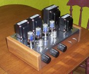
Here is a photograph.
I listen to mini-monitors, similar to Hatt-SE from Tony Gee. However, my listening room is a bit small, and I don't generally listen very loud. Power is enough for my needs. This amp is very simple and not too expensive. I used IAG chassis from Parts Connexion in Canada, but they seems to be sold out right now...
F
Attachments
- Status
- Not open for further replies.
- Home
- Amplifiers
- Tubes / Valves
- Trouble: Main transfo short?