Hi all....
I built a PP KT88 amp about a month ago and it´s been working fine to the other day when I noticed that the right channel sounded bubbly, like there was now power.
I measured at measuring points and got the following results:
I have 480V at B+, 465V at B++ and 350V at B+++. So Im a bit to high at B++ and B+++.
At the junktion of pin´s 3 and 8 of the ECC99 I have 107V, this should be 130V.
At measuring point 125V (after 1K res from pin 2 of ECC99) I have 108V
KT88´s are biased at 60mV.
Plate voltage on the ECC99s:
Tube 1: pin 1 275V, pin 6 320V
Tube 2: pin 1 300V, pin 6 271V
Today I noticed while poking around that the bias of the KT88´s was a tad to high so I started to adjust them but in the end the result was that all the KT88´s are now running at 95mv, and there is no way to turn the bias down. Very strange.
What could be the problem??
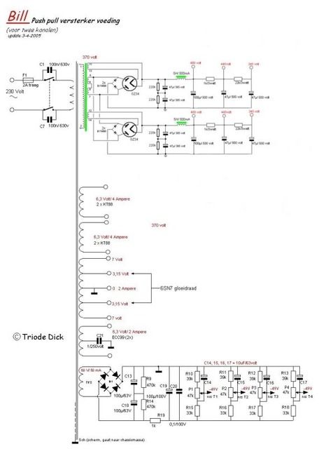
Note that this is NOT Triode Dicks original PS, this is a modded version.
Cheers
I built a PP KT88 amp about a month ago and it´s been working fine to the other day when I noticed that the right channel sounded bubbly, like there was now power.
I measured at measuring points and got the following results:
I have 480V at B+, 465V at B++ and 350V at B+++. So Im a bit to high at B++ and B+++.
At the junktion of pin´s 3 and 8 of the ECC99 I have 107V, this should be 130V.
At measuring point 125V (after 1K res from pin 2 of ECC99) I have 108V
KT88´s are biased at 60mV.
Plate voltage on the ECC99s:
Tube 1: pin 1 275V, pin 6 320V
Tube 2: pin 1 300V, pin 6 271V
Today I noticed while poking around that the bias of the KT88´s was a tad to high so I started to adjust them but in the end the result was that all the KT88´s are now running at 95mv, and there is no way to turn the bias down. Very strange.
What could be the problem??
Note that this is NOT Triode Dicks original PS, this is a modded version.
Cheers
Last edited:
Are you still getting the "bubbly" sound? That and the output stage current could be a sign of oscillation. Your driver stage DC voltages don't seem too far out of whack- the cathode voltage of the ECC99 will be a strong function of the current drawn by the 6SN7 input tube.
Check the voltages at the wipers of the bias adjustment pots to make sure that supply is still OK. If you have a scope, look at the amp output and at the power supply rails.
Check the voltages at the wipers of the bias adjustment pots to make sure that supply is still OK. If you have a scope, look at the amp output and at the power supply rails.
If you are measuring 107volts on the cathodes of the ecc99's and 108 volts at the grid they are biased at +1 volt on the grids which isn't good. I notice in your posted schematic the coupling capacitors to the grid of the kt88's are only rated at 400volts. These should be 600volt types, try removing them and recheck your voltages and see if they aren't leaking badly from overvoltage at turn on.
If you are measuring 107volts on the cathodes of the ecc99's and 108 volts at the grid they are biased at +1 volt on the grids which isn't good. I notice in your posted schematic the coupling capacitors to the grid of the kt88's are only rated at 400volts. These should be 600volt types, try removing them and recheck your voltages and see if they aren't leaking badly from overvoltage at turn on.
Hi jerluwoo
Yes, I forgot to mention that the cap´s are 0,33uf 500V, I did upgrade them. I use russian K42Y caps. Could they be sensetive to the heat? theay are placed under the tubes and it gets rather hot there, not untouchable but hot.
Could it be the tubes are fried? I did fry a pair while building the amp and I think the result was the same, bubbly sound with no power. This time I havn´t done anything and the amp has worked for some weeks with good sound, to now. I do have a bit high V on the ECC99 plates, could this be the pronlem?
Thanks
Hi,
Have you checked P1,P2,P3,P4 outputs? (What is the maximum -V you can get?)
How close to the maximum setting of bias voltage is the bias set to?
Does the bias drift or is it stable?
Have you still got a Gnd connection between the bias supply and the Amp Gnd?
Have you checked the Bias supply voltage?
Is the fault in both channels? (If it is then it's got to be something common to both)
If C2 & C3 are good then ECC99 should not effect the Bias!
Regards
M. Gregg
Last edited:
Just for interest,
If C2/C3 or the other channel were leaky you would get voltage from B+ on the bias supply via the trim pot. This would change the bias settings on the KT88's.
As jerluwoo suggests either remove the caps (C3/C2) or just to test change all (both channels) the KT88 coupling caps to some cheap polyproplene. Then try biasing the tubes and see what you get!
Regards
M. Gregg
Hi,
Have you checked P1,P2,P3,P4 outputs? (What is the maximum -V you can get?)
How close to the maximum setting of bias voltage is the bias set to?
Does the bias drift or is it stable?
Have you still got a Gnd connection between the bias supply and the Amp Gnd?
Have you checked the Bias supply voltage?
Is the fault in both channels? (If it is then it's got to be something common to both)
If C2 & C3 are good then ECC99 should not effect the Bias!
Regards
M. Gregg
Hi M Gregg
Have you checked P1,P2,P3,P4 outputs? (What is the maximum -V you can get?)
One P1 & P2 I have -50VDC and on P3 & P4 i have -43VDC
How close to the maximum setting of bias voltage is the bias set to?
On P1 & P2 I have some more to give but on P3 & P4 -43V is maximum
Does the bias drift or is it stable?
It doesn´t drift.
Have you still got a Gnd connection between the bias supply and the Amp Gnd?
Yes, from positive on bias control to negative ground.
Have you checked the Bias supply voltage?
It´s a bit higher than in the schematic, 60VAC
Is the fault in both channels? (If it is then it's got to be something common to both)
No it is only in one channel.
If C2 & C3 are good then ECC99 should not effect the Bias!
I changed C2 & C3 in the channel with bias problem but the problem is still there. Right channel biased at 60mv and left at 95/100 mv
Im lost....?
Thanks M Gregg
OK, pull the output tubes and the HV rectifier tubes, then repeat those measurements. If the numbers are substantially larger, you have a grid current problem in the output stage. If the voltages don't change, it's a bias supply problem.
I tried changeing C2 & C3 in the other channel but nothing happened. Still got bias problem in one channel.....
Im still lost
Cheers
Im still lost
Cheers
OK, pull the output tubes and the HV rectifier tubes, then repeat those measurements. If the numbers are substantially larger, you have a grid current problem in the output stage. If the voltages don't change, it's a bias supply problem.
Hi Sy
Ok, here goes measuring without power and rectifier tubes:
Same as before, P1 & P2 I have -50VDC and on P3 & P4 i have -43VDC
So this could be a biassupply problem.....
Is there any chance that if the ECC99´s are gonners that this would affect the bias?
Cheers
I disconnected the bias supply from everything and measured the max voltage and I get -60VDC an all pots P1, P2, P3, P4 so this is working.
Cheers
Cheers
OK, then, if your more recent post is what you're seeing (-60V max), your output stage is suspect. Could be leaky coupling caps (possible) or (much more likely) duff output tubes.
Ok, now Im getting somewhere....
I have connected the bias supply again and have perfect 60mv bias on all the KT88´s. Don´t ask me what I did because I don´t know.
Anyway, I still have deviant measurment results on junction testingpoint 130V, I measure 109V and 104V on right and left channel.
On measurement testingpoint 125V, I measure 109 and 106V on right and left channel.
What could be causing this?
Cheers
OK, then, if your more recent post is what you're seeing (-60V max), your output stage is suspect. Could be leaky coupling caps (possible) or (much more likely) duff output tubes.
Hi Sy
I have replaced all cap´s except C1 in both channels........
Brand new JJ KT88´s........
I changed output tubes to brand new EH KT88´s and measurments ar following:
Junction testingpoint 130V, I measure 107V and 102V on right and left channel.
Testingpoint 125V, I measure 108 and 105V on right and left channel.
??????
Cheers
Last edited:
OK, then, if your more recent post is what you're seeing (-60V max), your output stage is suspect. Could be leaky coupling caps (possible) or (much more likely) duff output tubes.
Sy
-60VDC is maximum from bias supply, minimum is -43VDC. Anyway this is sorted, all KT88´s are now biased at 60mv.
So the only problem is as post above.......
Thanks
Well, if bias is now back in range, you have something intermittent. Redo the solder connections around the output stage and bias controls, check the tube sockets.
Measure the grid-to-cathode voltages of the ECC99 directly (i.e., one probe on the cathode, one probe on the grid). See if the cathode is positive with respect to the grid (which it should be).
Measure the grid-to-cathode voltages of the ECC99 directly (i.e., one probe on the cathode, one probe on the grid). See if the cathode is positive with respect to the grid (which it should be).
Hi,
I think I would alter the Bias so that you can get at least -55V from the trim pots. You only need to get a slight problem and you are out of range!
If you are dropping the voltage so much when the tubes are in circuit there is something wrong. You only have the grid and a coupling cap connected. The bias at max to bias the O/p tubes is not good.
Regards
M. Gregg
On junction testingpoint 130V, I measure 109V and 104V on right and left channel.
On measurement testingpoint 125V, I measure 109 and 106V on right and left channel.
What could be causing this?
Remember that what you measure is not always the same as what is there when you do not measure - depending on the impedance of your measuring gear, and sometimes also noise injected.
Do what SY is suggesting to work around this.
SveinB
Well, if bias is now back in range, you have something intermittent. Redo the solder connections around the output stage and bias controls, check the tube sockets.
Measure the grid-to-cathode voltages of the ECC99 directly (i.e., one probe on the cathode, one probe on the grid). See if the cathode is positive with respect to the grid (which it should be).
Hi Sy
Ok, I have been poking about and resoldered all connections in OP.
I measured following:
Right channel ECC99
Pin 2, 102V
Pin 7, 92V
Left channel ECC99
Pin 2, 102V
Pin 7, 91V
Junction pin 3 & 8 ECC99 Right channel 98V
Junction pin 3 & 8 ECC99 Left channel 100V
Grid to cathode ECC99 right channel
Pin 2 to 3, 3V
Pin 7 to 8, 0V
Grid to cathode ECC99 left channel
Pin 2 to 3, 1,2V
Pin 7 to 8, 0V
I have no voltage from cathode at all?????
The plate voltages on the ECC99 are reasonable- the way this circuit is set up, there's roughly 6mA through each section and that's more or less what you're getting. The fact that the "zero bias" issue is common to both channels makes me a bit suspicious that your voltmeter may be perturbing the measurement. As it sits now, with the OP stage biasing working, does the amp pass signals without distortion?
- Status
- Not open for further replies.
- Home
- Amplifiers
- Tubes / Valves
- Troubble shooting help please.....