Hello,
To understand more easily and more faster the overall EPSUX3 structure, i've draw a simplified synoptic.
It show only functional blocks, that you can find on schematic for more details.
Regards.
EPSUX3V1 Synoptic.
Frex.
To understand more easily and more faster the overall EPSUX3 structure, i've draw a simplified synoptic.
It show only functional blocks, that you can find on schematic for more details.
Regards.
EPSUX3V1 Synoptic.
Frex.
Looks good Frex.
Question, why did you design the flyback transformer? because the three outputs? or better specifications, quality?
And the enclosure don't need a small cooling vent?
An externally hosted image should be here but it was not working when we last tested it.
Question, why did you design the flyback transformer? because the three outputs? or better specifications, quality?
And the enclosure don't need a small cooling vent?
Last edited:
Hello Carpin,
I design the transformer because you can't find already build transformer with your own specs !
Designing and building it is not a big problem for me.
I don't think that the case will need a fan. The enclosure is in extruded aluminium and it's thermal impedance is good.
Of course, only final tests at maximal power will verify this.
Regards.
Frex
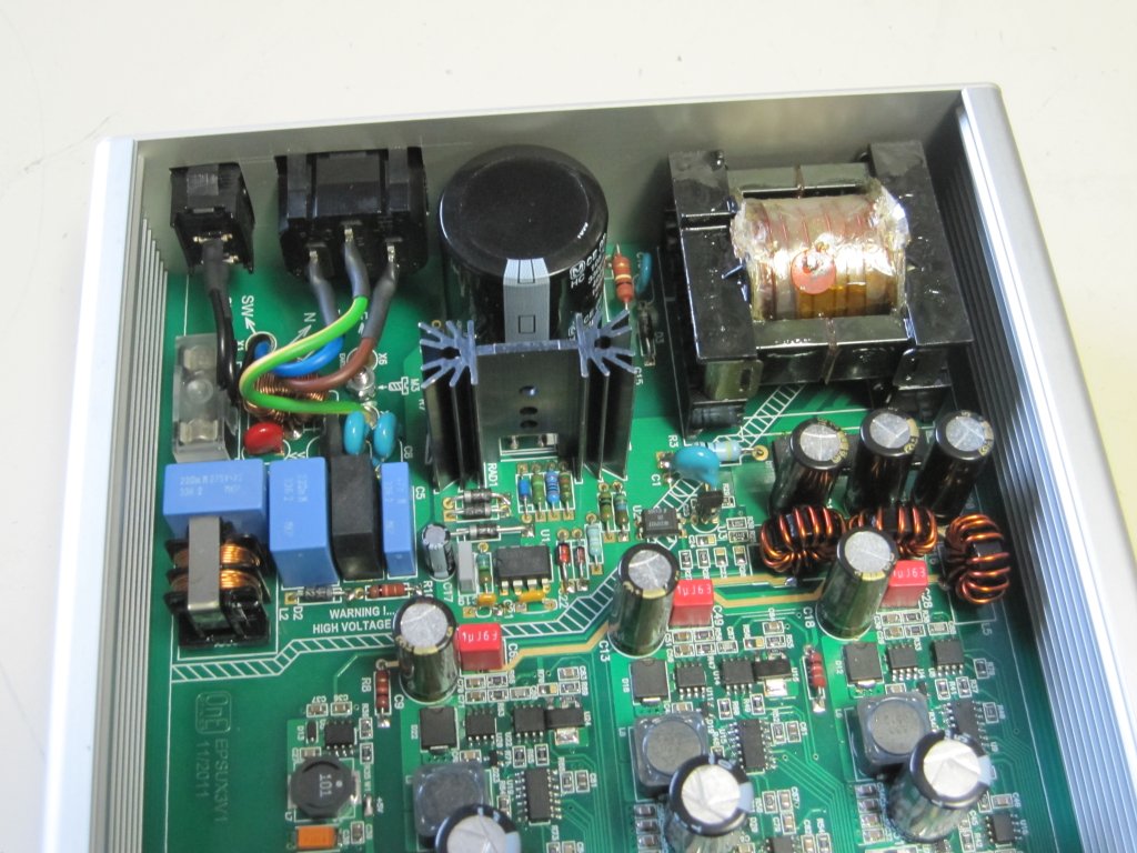
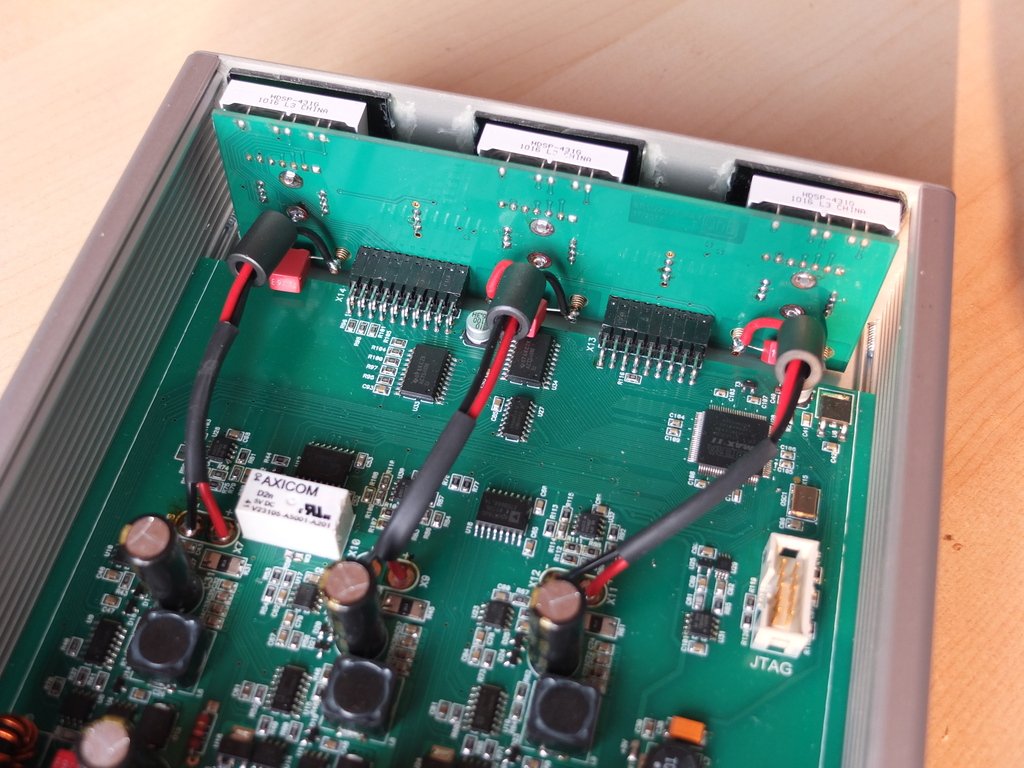
Hello,
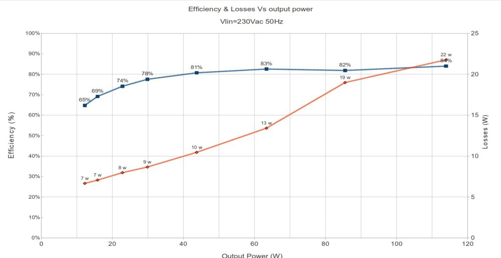
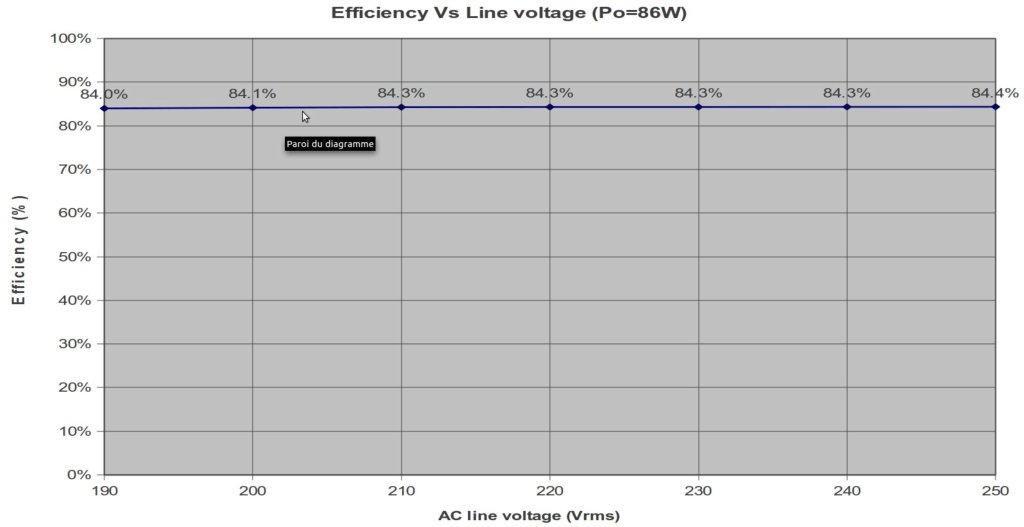
The full design is well advanced and the flyback transformer is now soldered and tested on the final board, and fully functional.
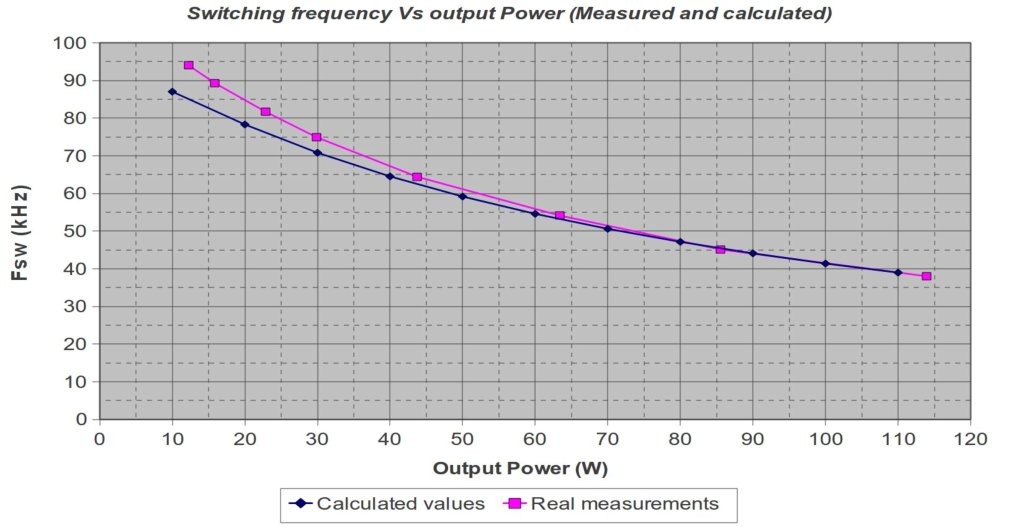
I have done many tests on the flyback, including measurements of efficiency vs Pout and vs Vline.
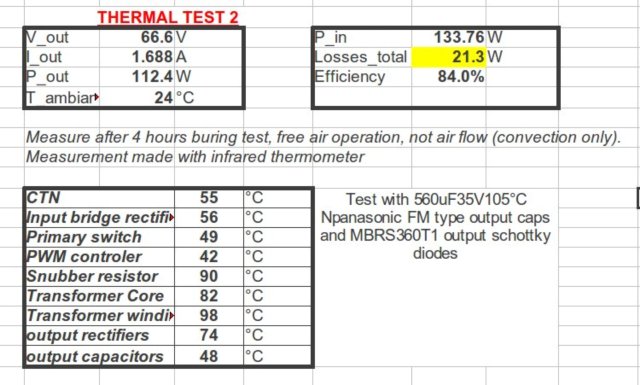
I have tested the short circuit and open loop conditions and thermal behaviour of power parts.
I will post complete graphs results tomorrow.
Some little modifications has been done (parts values) to optimise it.
Front panel is now also drilled.
You can show the design progression on pictures below.
Frex
The full design is well advanced and the flyback transformer is now soldered and tested on the final board, and fully functional.
I have done many tests on the flyback, including measurements of efficiency vs Pout and vs Vline.
I have tested the short circuit and open loop conditions and thermal behaviour of power parts.
I will post complete graphs results tomorrow.
Some little modifications has been done (parts values) to optimise it.
Front panel is now also drilled.
You can show the design progression on pictures below.
Frex
Nice work! Superbly professional.
Any ripple vs load and voltage deviation vs step load measurements?
Any ripple vs load and voltage deviation vs step load measurements?
Hi Tazzz,
Thank you for your comments.
These measurements are made on the flyback outputs, not final PSU outputs.
But yes, i will perform others measurements on the real PSU outputs, like ripple voltage and a 0.5A/1.5A load step transient response.
That's not yet finished ! 🙂
FRex
Thank you for your comments.
These measurements are made on the flyback outputs, not final PSU outputs.
But yes, i will perform others measurements on the real PSU outputs, like ripple voltage and a 0.5A/1.5A load step transient response.
That's not yet finished ! 🙂
FRex
Hi all,
The PSU project is still in progress. The front panel has been drilled.
No big issue has been encountered during mechanical mount.
The green plexiglass of the leds displays is too dark, i must find another.
I've also started to do some quick noise measurements, that show about 20 mV with
a purely sinusoidal profile.
I must d build a serious measurement setup to do these measurements with good confidence.
Frex
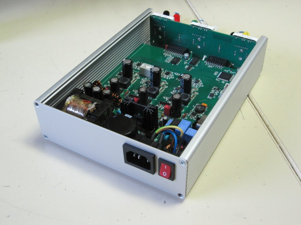
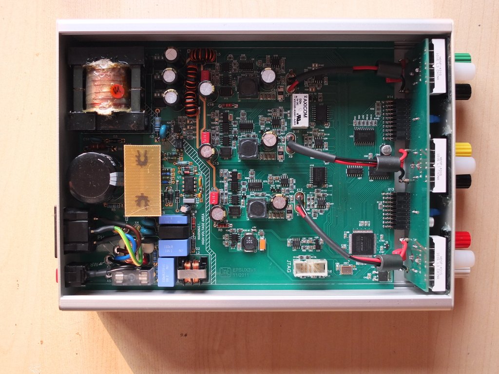
Hello,
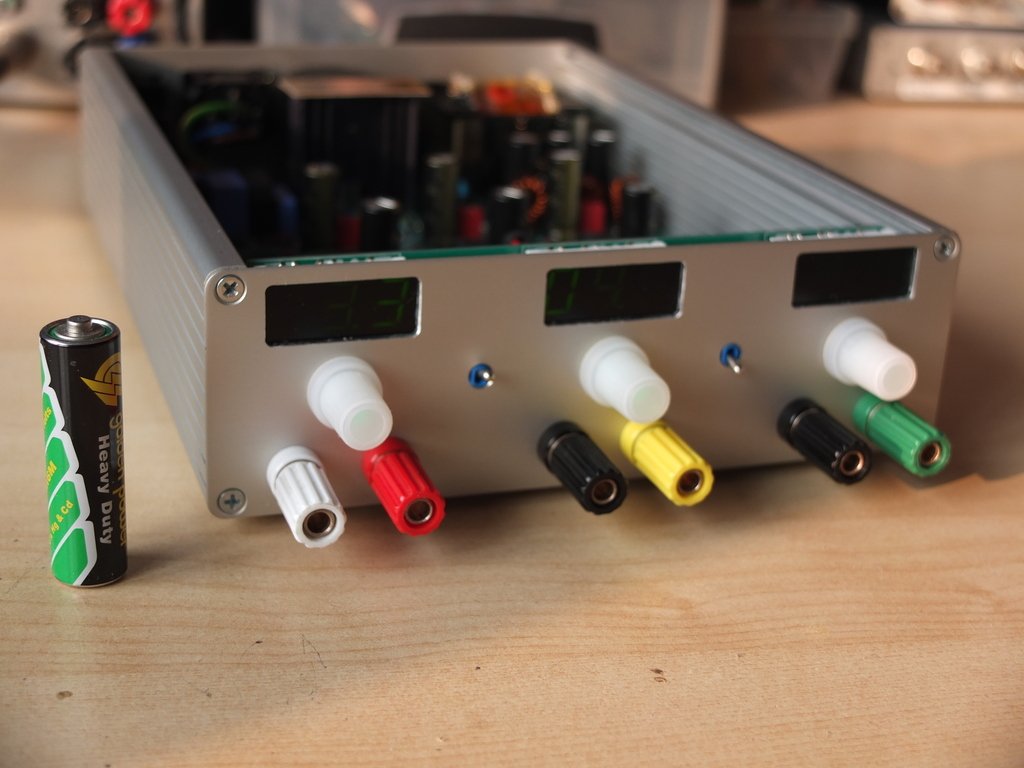
Some pictures of how it looks like now.
Frex
(it's an AA battery at left for size comparison)
Some pictures of how it looks like now.
Frex
(it's an AA battery at left for size comparison)
Hello all,
I've finally ordered a new set of drilled and engraved front and rear panel of the PSU to Schaeffer-ag.
I discover their services, and cost is very reasonable.
So, i wait these new panels, with color marking for a beautiful finishing.
I have find also another green windows that give a very good display result.
(i use a translucent green CD cover ! 🙂 ).
I've also made some tests, connecting PSU outputs in many serial configurations, and all pass successfully.
I don't have much time right now to perform all needed test, but i'll post any results as they become done.
Maybe, if some DIYers are interested to build this project, i could open a wiki page to summarize infos about it and create a list of potential builders.
Please, give me your feedback about that...
Regards.
FRex
Nice work, excellent handicraft.
Impressive that you wound your own off-line transformer, shows that you know what you are doing. I have a question refereing to the schematics-
D14,D19,D23 , what are their purpose ? the Vsense is at Vref (1,2 V aprox) ?
Impressive that you wound your own off-line transformer, shows that you know what you are doing. I have a question refereing to the schematics-
D14,D19,D23 , what are their purpose ? the Vsense is at Vref (1,2 V aprox) ?
Hi rikkitikkitavi,
Thank you for your interest.
The three zener diodes D14,D19 and D23 protect the TPS5450 feedback inputs from over-voltage. This is need because the OPAMP that drive these inputs is supplied from the buck input voltage (~22Vdc).
Normaly, i will receive my newly drilled and engraved panels from Schaeffer this thuesday...
That's cool....
Frex
Last edited:
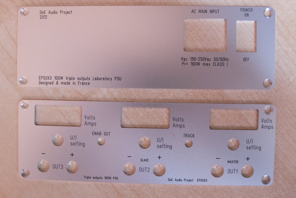
Hi all,
I've receive as expected my new front and rear panel from Scheaffer today.
It's the first time i use their service and i'm very impressed.
It's a very clean job as you can show below.
I will mount them tomorrow and new pictures will come soon.
Regards.
Frex
I've receive as expected my new front and rear panel from Scheaffer today.
It's the first time i use their service and i'm very impressed.
It's a very clean job as you can show below.
I will mount them tomorrow and new pictures will come soon.
Regards.
Frex
Hi merlin,
I will organize a PCB group buy and a wiki dedicated page when the project will be fully finished.
Frex
I will organize a PCB group buy and a wiki dedicated page when the project will be fully finished.
Frex
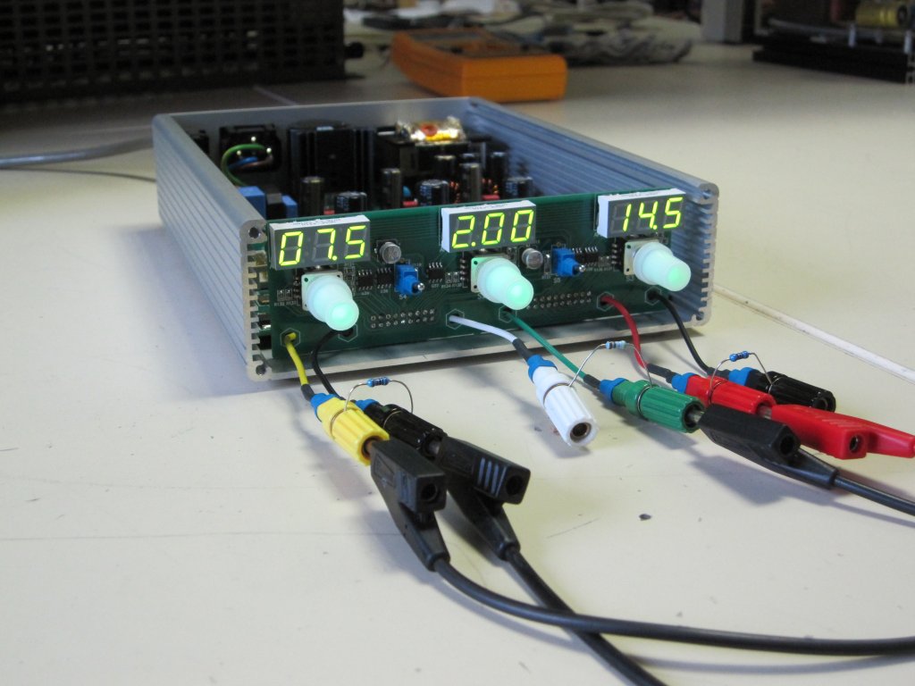
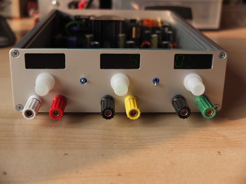
Hello all,
The new panel has been mounted now, they give a professional look of the PSU.
You can see the results on some pictures below.
-1 - Front view, off state.
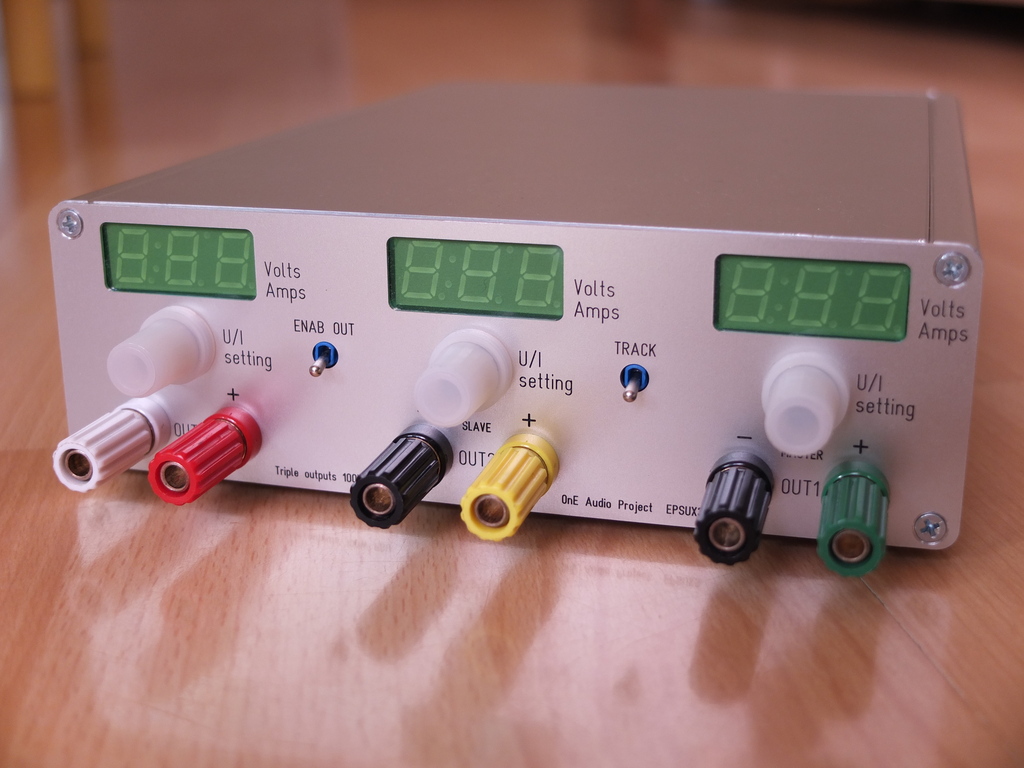
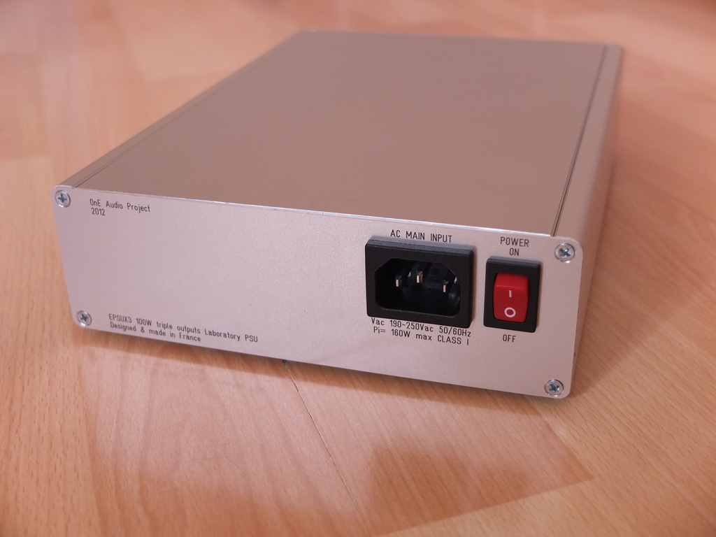
-2 - rear view.
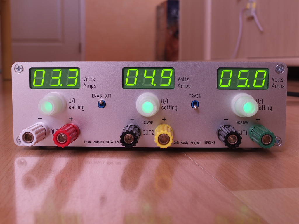
-3 - front view, on state.
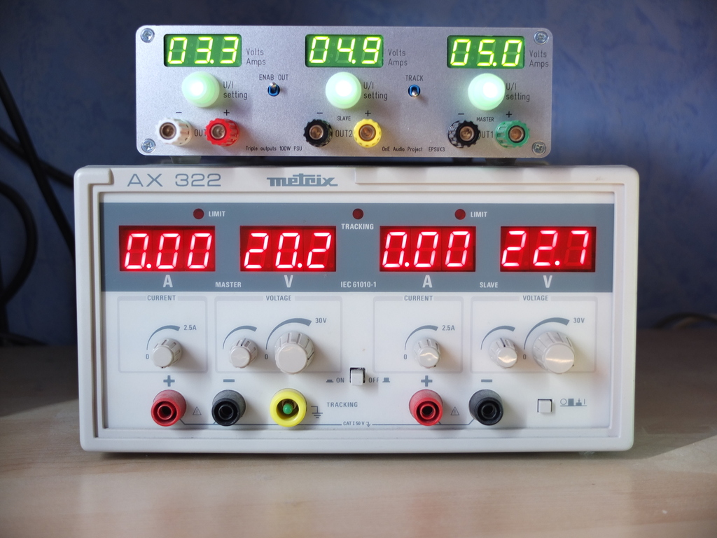
-4 - Front view with Metrix AX322 PSU for size comparison.
(The EPSUX3 is also very lighter than AX322!).
Before to terminate this design, i must optimize the current regulating loop that oscillate in some conditions. That will be only change some parts values.
Then after that, doing a complete and accurate measurements table for each output.
I've weigh the PSU (without cord) and it's only 1.2kG (2.64 pounds).
I hope to open the new wiki page for the PSU project very soon, and starting to take the name of interested DIYers to get the PCB.
Because i understand that building the flyback transformer can be a barrier to build this PSU project, if enough buyers are interested i could try to order the transformer to a manufacturer.
Frex.
(I've already start a new project, a power amplifier for my squeezbox Touch, but you be informed about it later. 😉 )
The new panel has been mounted now, they give a professional look of the PSU.
You can see the results on some pictures below.
-1 - Front view, off state.
-2 - rear view.
-3 - front view, on state.
-4 - Front view with Metrix AX322 PSU for size comparison.
(The EPSUX3 is also very lighter than AX322!).
Before to terminate this design, i must optimize the current regulating loop that oscillate in some conditions. That will be only change some parts values.
Then after that, doing a complete and accurate measurements table for each output.
I've weigh the PSU (without cord) and it's only 1.2kG (2.64 pounds).
I hope to open the new wiki page for the PSU project very soon, and starting to take the name of interested DIYers to get the PCB.
Because i understand that building the flyback transformer can be a barrier to build this PSU project, if enough buyers are interested i could try to order the transformer to a manufacturer.
Frex.
(I've already start a new project, a power amplifier for my squeezbox Touch, but you be informed about it later. 😉 )
That looks great. I could use a bench power supply. Awesome work on the case too.
Are you going to make the boards or kit available?
Are you going to make the boards or kit available?
- Status
- Not open for further replies.
- Home
- Design & Build
- Equipment & Tools
- Triple outputs 100W Laboratory PSU -- A new DIY project .