Hi all,
I am working on a Harman Kardon integrated amp HK6950r. The pre-amp works fine and the power section would on power up either work for a few minutes or just directly trigger the protection circuit.
I have isolated it to one channel where the output stage current jumps up enough to trigger the protection circuit via Q477 or Q478 (not sure why there are two labels). I noticed that when I take the power amp section of of the chassis, that symptom goes away and the amp continues to operate. Soon as the heatsink touches the chassis, the protection circuit trips from the one channel.
I have tried a number of things. I replace most of the caps on the amp and adding bypassing via surface mount caps, installing base resistors between 0.5 to 4.7 ohms per device and even doubling the Miller cap on the driver stage. Nothing helped and with all those in place, even the good channel does not operate.
Any suggestions? Unfortunately I do not have a functional scope so DVM is what I have to work with (and a lot of patience...) Many thanks!
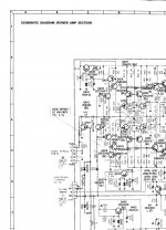
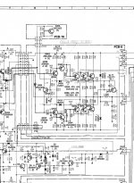
Here are the two pages for the power stage. I apologize for the page break but that is how the manual comes.
I am working on a Harman Kardon integrated amp HK6950r. The pre-amp works fine and the power section would on power up either work for a few minutes or just directly trigger the protection circuit.
I have isolated it to one channel where the output stage current jumps up enough to trigger the protection circuit via Q477 or Q478 (not sure why there are two labels). I noticed that when I take the power amp section of of the chassis, that symptom goes away and the amp continues to operate. Soon as the heatsink touches the chassis, the protection circuit trips from the one channel.
I have tried a number of things. I replace most of the caps on the amp and adding bypassing via surface mount caps, installing base resistors between 0.5 to 4.7 ohms per device and even doubling the Miller cap on the driver stage. Nothing helped and with all those in place, even the good channel does not operate.
Any suggestions? Unfortunately I do not have a functional scope so DVM is what I have to work with (and a lot of patience...) Many thanks!
Here are the two pages for the power stage. I apologize for the page break but that is how the manual comes.
Attachments
Maybe I can add a couple of things. The protection circuit disables the input biasing via Q405 (prot signal line). I tried disconnecting that line to see if it was some kind of spurious operation but no, the main fuse (8A) blows every time I tried that so current was indeed being pulled.
I know this sounds too simple, but check for a bad insulator on one of the outputs.
I ran home from work to check this out. Wouldn't this be great! Unfortunately (for me), I changed out the pads and same thing. Now I notice that even if the amp would power up to work, soon as I touch the heatsink, the protection kicks in. Could it be some kind of oscillation?
Member
Joined 2009
Paid Member
I have read that people have experienced issues with oscillations through poorly grounded heatsinks.
Normally the amplifier ground is isolated from the chasis via a 'protected earth' circuit - essentially a pair of back to back parallel diodes. This is to reduce the possibility of earth loops which create 'hummmmm'. If the heatsink isn't already inadvertently connected to something it should be then you could try connecting the heatsink to the amplifier ground - not the chassis. Hopefully they are not the same thing in your amp.
Normally the amplifier ground is isolated from the chasis via a 'protected earth' circuit - essentially a pair of back to back parallel diodes. This is to reduce the possibility of earth loops which create 'hummmmm'. If the heatsink isn't already inadvertently connected to something it should be then you could try connecting the heatsink to the amplifier ground - not the chassis. Hopefully they are not the same thing in your amp.
I have read that people have experienced issues with oscillations through poorly grounded heatsinks.
Normally the amplifier ground is isolated from the chasis via a 'protected earth' circuit - essentially a pair of back to back parallel diodes. This is to reduce the possibility of earth loops which create 'hummmmm'. If the heatsink isn't already inadvertently connected to something it should be then you could try connecting the heatsink to the amplifier ground - not the chassis. Hopefully they are not the same thing in your amp.
Thanks for your input. As luck would have it, the way HK did the grounding is that they star grounded at the heatsink between the two channels already.
In my digging, I found some comments about the critical nature of C413 and C469 (cap between the sources of the input FETs and between the emitters of the driver output. Does anyone have any thoughts about how these might affect stability of the amp?
Is there a cap between the two LTPs ?? Could you icrease the size of the schematic to have a closer look at it ??
I can suggest for now the use of a small cap of around 10 to 15pf between the two bases of the ccs s feeding the LTPs just to be sure the problem doesnt start here.
Btw I dont like this outputstage much, the use of those inductors together with miller caps on the drivers and a nonlinear capacitance with the diode in the cfps is just asking for trouble. I can see why later models used different setups.
@homemodder, I took the liberty of emailing the pdf file to you. The schematics is toward the end of the file. Otherwise I am not sure I can improve on the readibility.
If you would not mind, can you let me know the exact nodes where I should attach the 15p cap you mentioned?
You mentioned HK's later modelling having a different set up. Is that easy enough to "upgrade" to?
Many thanks!
If you would not mind, can you let me know the exact nodes where I should attach the 15p cap you mentioned?
You mentioned HK's later modelling having a different set up. Is that easy enough to "upgrade" to?
Many thanks!
No problem, I have found a way to get a clear view.
The cap I suggest is between the bases of Q407 and Q419 and also one between Q409 and Q415. Try small value but if dont help you could use a value upto 100 pf.
Ill try post a schematic from another HK model tommorrow. The outputstage is the same setup but without some of those passive parts. I never use those inductors to the outputs with cfp drivers and have never had any problems although HK seem to persist with this.
I am busy with work stuff so probably won't get to the amp tonight. ;-( but it would be good to see if I should change the output stage to the later design from your schematics.
Thanks!
Thanks!
@homemodder, I soldered a 24pF cap across the bases as you suggested (4 of them). The main fuse blew a couple of times (ie the protection circuit now seems not to be able to current limit in time)
Any help or tips would be appreciated.
Any help or tips would be appreciated.
@homemodder, I soldered a 24pF cap across the bases as you suggested (4 of them). The main fuse blew a couple of times (ie the protection circuit now seems not to be able to current limit in time)
Any help or tips would be appreciated.

The only efect those caps do is to stabilize the current source, in effect its a cdom applied to a current source.
Can you try placing the cap between the base and the collector of Q419 and the same with the other current source.
Last edited:
I soldered a 24p cap as suggested in post 13. No dice, main power fuse still blows.
I am thinking of taking the assembly and put on a variable power supply to debug. How do I "defeat" the protection signal to turn on the current source permanently? Anything else I need to do to enable the entire amplifier?
I am thinking of taking the assembly and put on a variable power supply to debug. How do I "defeat" the protection signal to turn on the current source permanently? Anything else I need to do to enable the entire amplifier?
Maybe you should NOT use and external supply or defeat the protection until you understand what is going on. You might just cause a beefier external supply and lack of protection to cause a small 'catastrophe!'
Right now all you do is change blown fuses all else remaining apparently safe !
Spend more time over the circuit and probe the circuit/parts till you get some idea. Don't have a scope or access to one ?
Cheers.
Edit: Does the fuse blow if you connect the heatsink to the chassis via a resistor ? start with 100ohms and going down to say 10 ohms.
Last edited:
Hello ashok,
Thanks for the suggestion. Luckily, my external power supply is dc variable dual power supply with current limiting. I was thinking I would slowly increase the power supply and get the working channel working and get the proper voltages etc and then slowly debug the other non-functional one with the current limited power supply. Right now, I am blowing fuses on power up. I do not have a scope but even if I had one, the fuse would have blown before I can read anything.
Thanks for the suggestion. Luckily, my external power supply is dc variable dual power supply with current limiting. I was thinking I would slowly increase the power supply and get the working channel working and get the proper voltages etc and then slowly debug the other non-functional one with the current limited power supply. Right now, I am blowing fuses on power up. I do not have a scope but even if I had one, the fuse would have blown before I can read anything.
Some circuits are not happy with supplies that ramp up very slowly . They do need sufficiently higher voltages , closer to normal operation , before things settle down. So below some threshold voltage things might be very unpredictable. So maybe you shouldn't start with too low a voltage and you shouldn't possibly keep 'varying' it slowly when it is powered up. Maybe !
If I were you, I'd spend more time studying the circuit before powering it up again. You could get some idea of how the currents flow and look for defective parts. Maybe it's just the bias section with defective parts ! Check the parts on board /and off board if required. Bias pots can give trouble. So many possibilities that you can check without powering up again. However you need 'time' .😉
You could also disable the bias section ( 0 V ) that will turn off the output transistors dc bias but show if everything else is operational. So lots of small things you can try out.
Last edited:
Do you are sure that you do not have a conection from transistor to heatsink?
Remove the heatsink from case and check with an multimeter from transistor (every pin) to heatsink the resistance.
In the meen time, during the all testing, connect in place of fuse a resistor of 10-100Ω(470)/16W to protect the output transistors.
Remove the heatsink from case and check with an multimeter from transistor (every pin) to heatsink the resistance.
In the meen time, during the all testing, connect in place of fuse a resistor of 10-100Ω(470)/16W to protect the output transistors.
@sesebe, thanks for the suggestion. Yes, I did check connection between power devices and heatsink. I even dissembled the heatsink and replaced the mica as well.
@ashok, I am in the process of checking single transistor in the driver and power sections. I agree it is something in the biasing circuit since the power fuse only blows after the soft start circuit times out. The wierd thing is that some time ago, the unit would even operate with the heat sink disconnected from the chassis. Soon as it touches, the bias current on one channel would jump and the fuse blows.
@ashok, I am in the process of checking single transistor in the driver and power sections. I agree it is something in the biasing circuit since the power fuse only blows after the soft start circuit times out. The wierd thing is that some time ago, the unit would even operate with the heat sink disconnected from the chassis. Soon as it touches, the bias current on one channel would jump and the fuse blows.
- Status
- Not open for further replies.
- Home
- Amplifiers
- Solid State
- Triple compound output amp stability