How could it be otherwise?
If you can greatly simplify the amp and get much improved objective performance at the same time, then it is a great use of synergistic effects. This is a great example of the pure genius of Nelson Pass!
A simple amp without cascaded voltage gain stages and global negative feedback tends to sound much better in many ways, and here we get a much improved total THD from the speakers for free.... Both better subjective and objective sound quality....
What's not to like about that???
"How could it be otherwise?"
Plenty of ways. You can control acceleration, velocity, position, even air pressure.
Air pressure is my favorite.....

Plenty of ways. You can control acceleration, velocity, position, even air pressure.
Air pressure is my favorite.....
Last year, I casually measured speaker distortion after adding digitally generated positive H2 (Blue), negative H2 (Red), No H2 (Green). 2 way speaker crossed around 850Hz, tweeter is connected in negative polarity. I don't remember why it is showing only 100Hz-5.85Khz.
Attachments
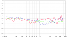
Just based on that distortion graph I would go with the blue line. More distortion at lower frequencies where positive going second harmonic will add some "forward projection" and a more vivid character, and less distortion in the very sensitive mid and upper midrange where distortion usually just sound "distorted", muddied and with less resolution or a sharp unnatural "definition" depending on the bell modes and break up of the loudspeaker cone.
Just based on that distortion graph I would go with the blue line. More distortion at lower frequencies where positive going second harmonic will add some "forward projection" and a more vivid character, and less distortion in the very sensitive mid and upper midrange where distortion usually just sound "distorted", muddied and with less resolution or a sharp unnatural "definition" depending on the bell modes and break up of the loudspeaker cone.
100% agreed. Now I only add positive H2 (Blue) for woofers, no H2 for tweeter. 🙂

I used this simple amp in the previous distortion measurements in this thread.

Some thinking and a large transformer core based choke led to this schematic.

15 kg transformer core choke.

7 parts makes for a fast and easy point to point build.

A simple prototype is enough to get a sense of the potential performance and some measurements.

Here is the measured response and THD through a Dayton Audio PS95-8 in a closed box.
I don´t have many enough of IRFP7430 to get a closely matched pairs at the moment, so I have to accept 30 mV DC offset over the choke.
I think this is the best sounding amp I have ever heard.

Here is a distortion measurement of the amp driving a cheap car audio 10 inch driver in a HROAR bandpass box. 0,623% THD at 40 Hz 101,7 dB at one meter.
I think it is a quite impressive performance considering that you seldom use simple single stage class A amps to drive car audio drivers and subwoofers.
It is not often you go shopping for a 5 volt powersupply when building amps, but it is enough for 2 watts into 8 ohms.
Do you need such a high transconductance as the IRFP7430 ?
could I go wuth a P channel with gm of 2 at 1A bias?
could I go wuth a P channel with gm of 2 at 1A bias?
With a high transconductance device like the IRFP7430 or IRFPS3810 you get a quite different character compared to an IRFP240 or IRFP9140 (P-channel).
I have tested several different Mosfets in this or reasonably similar layouts recently, and the IRFP7430 gives a very powerful and punchy character full of organic "life" and a very vivid and "forward" presentation. This is the way I prefer to voice my amp, but I don´t think it suits everybody.
Choosing the right device for you takes some hands on experimenting and testing. Any TO-247 device with a Vgs between 3 volts and 6 volts for 1 - 3 ampere through it will be technically suitable for this kind of amp. One must adjust the voltage over the amp to get the intended quiescent current.
It needs a adjustable regulated power supply. A Mean Well LRS-75-5 switched power supply seems quite suitable and cheap.

Here is a simulation of the amp with a pair of IRFP240 Mosfets. Low transconductance and non-triody.
Quite nice simulated performance with almost 15 volt output from a 5,3 volt power supply.
I have tested several different Mosfets in this or reasonably similar layouts recently, and the IRFP7430 gives a very powerful and punchy character full of organic "life" and a very vivid and "forward" presentation. This is the way I prefer to voice my amp, but I don´t think it suits everybody.
Choosing the right device for you takes some hands on experimenting and testing. Any TO-247 device with a Vgs between 3 volts and 6 volts for 1 - 3 ampere through it will be technically suitable for this kind of amp. One must adjust the voltage over the amp to get the intended quiescent current.
It needs a adjustable regulated power supply. A Mean Well LRS-75-5 switched power supply seems quite suitable and cheap.
Here is a simulation of the amp with a pair of IRFP240 Mosfets. Low transconductance and non-triody.
Quite nice simulated performance with almost 15 volt output from a 5,3 volt power supply.
I have many FQP7P06 P channel so that I could find a matched pair....
and coupling directly with my dac output wich has 2.5V DC on it, I increase bias voltage across S and D of the mosfet to 4+2.5= 7.5V
so maybe I could go with a 9V PSU
This gives more headroom to the mosfet...
Is my idea correct?
and coupling directly with my dac output wich has 2.5V DC on it, I increase bias voltage across S and D of the mosfet to 4+2.5= 7.5V
so maybe I could go with a 9V PSU
This gives more headroom to the mosfet...
Is my idea correct?
This gives more headroom to the mosfet...
Is my idea correct?
It will also depend on the DC resistance of your choke. It needs two windings bifilarly winded. Mine has 0,55 ohms per winding and 0,205 volts and 0,185 volts over the two windings (for a slight DC asymmetry due to the mismatched IRFP7430).
9 volts should work if the DCR of the windings are right. It is best to use an adjustable powersupply.
EPS-65-MEAN WELL Switching Power Supply Manufacturer
Something like the EPS-65-7.5-C might be suitable. My amp runs 0,72 ampere through the two IRFP7430 with only 4,11 Volts from the powersupply and 2,15 ampere from 5,1 volts. It is quite sensitive since there is so little resistance in the circuit.
I can´t really comment on the FQP7P06. They might be a little weak, but the only thing that will happen is that the amp distorts. Please try them if you have them lying around.

I used the device closest to your FQP7P06 in the LTSpice library, and it seems to work as intended in spice at least.
With 1,0 Ohm DCR in each winding and a 9,0 volt powersupply there runs 1,94 ampere through each mosfet. Each mosfet needs to dissipate roughly 15 watts of heat. This is with + 2,5 volts DC on the gate of each of the mosfet.
yes for sure I will use a meanwell variable psu (7 to 10V) and adjust for suitable bias (1A per device in a first step)
I will try it as soon as possible and report
Will use a normal 100VA EI transformer 12+12V secondary.... DC magnetic flux should cancel each other
I will try it as soon as possible and report
Will use a normal 100VA EI transformer 12+12V secondary.... DC magnetic flux should cancel each other
- Status
- Not open for further replies.
- Home
- Amplifiers
- Pass Labs
- "Triodity" to cancel loudspeaker distortion