In phono and line level preamps, I've seen triode-wired pentodes wired up with the suppressor grid tied to the cathode or the suppressor grid tied to the plate (along with the screen grid).
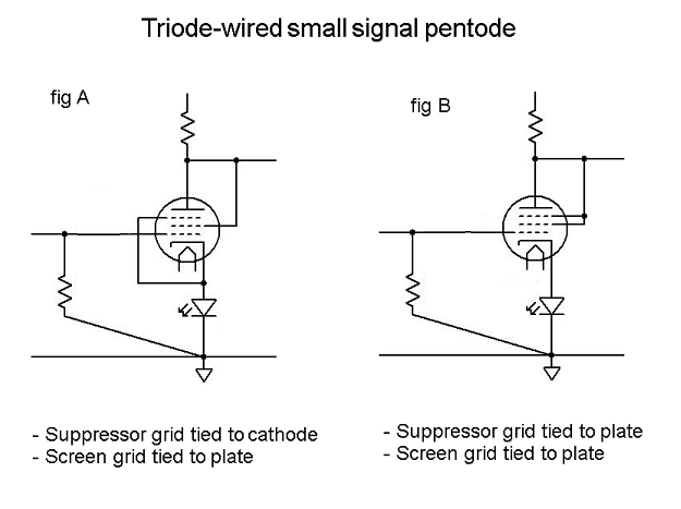
I can't seem to find a discussion of why you'd choose one over the other. I've seen that power output pentodes or beam tubes like EL34, 6L6GC, etc. are always wired with the suppressor grid to the cathode. But 5879, EF86, etc. are often wired with the suppressor to the plate, along with the screen grid.
Can anyone explain the differences, advantages, disadvantages of the two? Are there situations where one might be preferred over the other?
Thanks...
--
The effect would be similar to remote cut-off triode. Triode strapped pentode is a little bit remote cut-off. The more uniform distances between grid and cathode and grid to anode are, the more uniforn is field density where grid controls electric field, the more smooth is resulting tube. I also prefer tubes with longer structures. Like, 6N6P VS 6N3P: measure and compare results.
Wow, I read thru all that stuff in the other threads and could not come to a definitive conclusion either way. Testing doesn't show much of a difference between the two. The "spray" of low-level upper harmonic distortions generated in an EL34 triode with G3 connected to the plate does give me pause. I might leave things with G3 connected to cathode. That saves the bother of installing one more resistor (G3 grid stopper to plate).
I guess the jury's still out on this one.
--
I guess the jury's still out on this one.
--
For grins, go look at the D3a datasheet. It shows triode data connected both ways. The differences are subtle to say the least.
I have tried both ways many times with small signal pentodes,but not with power pentodes(yet!). I could not hear any difference or observe any in operation. There is,or was, somewhere on the internet, a substantial article, with lots of measurements and graphs, of the various possibilities for connecting pentodes.I remember it being quite hard to find-very sensitive to the wording of the search. One might feel instinctively that if you want a triode,more or less,then it will be more of a triode if all the superfluous grids are co-opted to the anode. It is entirely possible that what I have just said is unadulterated nonsense and I am prepared to be shot down in flames by any of the learned gentlemen above!
In phono and line level preamps, I've seen triode-wired pentodes wired up with the suppressor grid tied to the cathode or the suppressor grid tied to the plate (along with the screen grid).
--
In one case you have a triode wired pentode and in another you have a tetrode wirted pentode.
This topic was discussed here. They remind us that g3 is there to deal with secondary emission from the anode, especially when the anode is at a lower voltage than g2, and stop secondaries from going to g2. If g2 and the anode are connected together, then it doesn't really matter which electrode catches the secondary electrons. So the original purpose of g3 has gone.
It is usually a fairly open grid, with little effect on the electron stream, so it doesn't matter too much for small signal valves. For power valves there is the complication that g3 is not designed to dissipate any power so it ought not to be used for catching electrons, so connect it to the cathode.
piano3 may have seen the same article that I saw, but I can't find it either. Possibly Radiotron handbook?
Would it perhaps be wishful thinking to suppose that if electrodes are connected to the same potential then they will capture electrons in proportion to the area which they present? Therefore in practice they would be unlikely to exceed their power rating?
For power valves there is the complication that g3 is not designed to dissipate any power so it ought not to be used for catching electrons, so connect it to the cathode.
A very good point.
Hi,
the difference of g3 connection when triode-strapping a pentode or BPT will be nothing else but a horizontal shift of the curves, see attachment below, which is from my ETF06 lecture on triode-strapping pentodes and BPTs. You can get the very same effect just by changing the g1 bias voltage a little bit.
The g3 dissipation argument is void, since it doesn't consider the true area ratios of anode, surpressor and screen. As an approximation, just divide the allowed anode dissipation by the anode/g3 area ratio and you will see how low the power load of the g3 will be when strapping it to the anode. IOW, you just don't need to care 🙂
Regards,
Tom Schlangen
Attachments
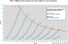
As you can see, curves are not gust shifted. Less uniform control structure causes less smooth transfer function, that you can see analyzing harmonics.
Hi Wavebourn,
Please note how small the change is. The difference in anode current when changing g3 connection is well within manufacturing tolerances of the same tube, connected the same way. Hence transfer function change and harmonic spectrum change also will be in the same range as expected by manufacturing tolerances. For all practical purposes, it is just a minor anode current shift (caused by the g3 area added to the effective anode area at the same potential).
If you have made systematic analysis of transfer functions and harmonics in this context under discussion and still think otherwise, please publish your results and explain their relevance compared to changes caused just by manufacturing tolerances. I would be most happy to learn more about it and I have no problem being corrected.
Regards,
Tom
As you can see, curves are not gust shifted. Less uniform control structure causes less smooth transfer function, that you can see analyzing harmonics.
Please note how small the change is. The difference in anode current when changing g3 connection is well within manufacturing tolerances of the same tube, connected the same way. Hence transfer function change and harmonic spectrum change also will be in the same range as expected by manufacturing tolerances. For all practical purposes, it is just a minor anode current shift (caused by the g3 area added to the effective anode area at the same potential).
If you have made systematic analysis of transfer functions and harmonics in this context under discussion and still think otherwise, please publish your results and explain their relevance compared to changes caused just by manufacturing tolerances. I would be most happy to learn more about it and I have no problem being corrected.
Regards,
Tom
Ok, one more hit. It is a diode. Why such curves given, and what it was used for?
Strange... I was intended to post it into the mystery device topic! 🙂
For all practical purposes, it is just a minor anode current shift (caused by the g3 area added to the effective anode area at the same potential).
I did not mean potential, I meant electric field & geometry.
What is the difference between sharp cut-off tubes and remote cut-off tubes?
Hi,
the difference of g3 connection when triode-strapping a pentode or BPT will be nothing else but a horizontal shift of the curves, see attachment below, which is from my ETF06 lecture on triode-strapping pentodes and BPTs. You can get the very same effect just by changing the g1 bias voltage a little bit.
The g3 dissipation argument is void, since it doesn't consider the true area ratios of anode, surpressor and screen. As an approximation, just divide the allowed anode dissipation by the anode/g3 area ratio and you will see how low the power load of the g3 will be when strapping it to the anode. IOW, you just don't need to care 🙂
Regards,
Tom Schlangen
Hehe I was just about to mention this as I have the PDF from this lecture 🙂
If you look closely at the righthand side of the graph, it shows that curves are just slightly steeper, in other words, more transconductance. However, for 99% of all pentodes the difference is truly minimal. One that comes to mind where the difference is a few % is the 12Zh1L 'universal' pentode (RL12P2000 clone IIRC?).
Two thoughts that come to mind regarding G3 strapping:
1) BPTs should always have G3 connected to a potential close to the cathode. The reason for this is there is no G3, rather there are beam plates, which form the electron stream cross-section in one of 3 dimensions - making them pass through the grids at a point relatively far from the grid supports where the grid cannot be considered a linear 'louvre' array of sorts. However, in a triode-strapped BPT, G2 encloses G1 and is not static any more, so it's a given that the beam from cathode to anode varies in cross section regardless of the beam formers being at a static potential close to the cathode.
2) In a few tubes the internal wiring is organized with G3 assumed to be close to cathode potential and well decoupled to the cathode or to a common ground, so it acts as an internal shield. Strapping G3 to the anode will certainly alter capacitances, depending on voltages present may cause problems with flash-over, and at extremes a possibility of self-oscillation is not out of the question.
As for strapping G3 to anode making the tube more 'remote cut off', I don't see it as it's not a control grid, and it's very sparse compared to G2. It does make for irregularity in the length of electron travel, but were not talking GHz here. As I see it' it just adds a little more anode area closer to G1, making the tube appear as sort of 3 tubes in parallel, one with G2 as anode, one with G3 as anode and one with the actual anode as anode. Of course, there would be inter-relations but G3 would have to be the least influential grid in this case.
That being said, using multiple grids as G1 indeed does produce a more remote cut-off effect, because looking from the cathode into the anode through the grids, it introduces anomalies in effective grid pitch and distance. Again, G3 would add the mist subtle effect given it's the one with the largest pitch by far and furthest from the cathode. If one takes this into account when triode strapping the pentode, this same effect would be seen greatly attenuated as the composite G2, G3, A 'anode' is also a 'voltage feedback' input. It follows then that the effects of G3 being strapped to the anode would be the most attenuated.
Take an EL34, it can be a very hard sounding valve in push-pull with 450v HT. In SE mode its much sweeter but in a SE triode schenario with a lower HT it will sound super sweet, but maybe a little mush in detail as the grids are not doing the job they where made for. If you want SE then use a 300B.
I have two 300B output transformers I picked up very cheap but they are 3.5k instead of 5k so I'm going to make an EL34 amp with them. I was tempted to go triode but the EL34 sounds very sweet single ended and it's pentode topology will add greater aplomb.
I have two 300B output transformers I picked up very cheap but they are 3.5k instead of 5k so I'm going to make an EL34 amp with them. I was tempted to go triode but the EL34 sounds very sweet single ended and it's pentode topology will add greater aplomb.
Take an EL34, it can be a very hard sounding valve in push-pull with 450v HT. In SE mode its much sweeter but in a SE triode schenario with a lower HT it will sound super sweet...
Can these three different sound genres (hard, sweet and super sweet) be separated by measuring/analyzing THD, frequency response or something else ?
- Status
- Not open for further replies.
- Home
- Amplifiers
- Tubes / Valves
- Triode-wired small signal pentode question