In my travels on the information super highway, I came across this gem. It emulates a triode using silicon, with nary a piece of glass in sight.
Triode Emulator by Dimitri Danyuk
I was in two minds on where to post this thread. The silicon guys might ignore it and the tube/valve guys might regard it as heresy.
Nevertheless, it has attracted very little attention and I was wondering why. It seems like such a good piece of research. I mean, it was accepted by theAudio Engineering Society for their 2004 convention. It has only been mentioned in passing on this forum.
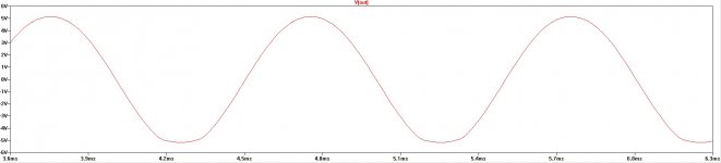
I have run the circuit in LTspice and it works as advertised. The clipping behavior resembles that of a valve amp.
Any thoughts?
Triode Emulator by Dimitri Danyuk
I was in two minds on where to post this thread. The silicon guys might ignore it and the tube/valve guys might regard it as heresy.
Nevertheless, it has attracted very little attention and I was wondering why. It seems like such a good piece of research. I mean, it was accepted by theAudio Engineering Society for their 2004 convention. It has only been mentioned in passing on this forum.
I have run the circuit in LTspice and it works as advertised. The clipping behavior resembles that of a valve amp.
Any thoughts?
Attachments

Last edited:
OMG,
Sure looks complicated!
Just use a Mosfet with Schade feedback (a drain to gate resistor and a 2nd resistor from input to the gate). Operated up at the right current level, they can even operate with near 3/2 power law.
But typical tubes have grid1 so close to the cathode that the grid structure wire "shadow" effects make them operate closer to square law mode anyway (and that's native mode for the Mosfet).
Hence their mostly 2nd harmonic distortion signature.
If you want less gm, then put a TV damper diode in series with the Source terminal of the Mosfet.
Last edited:
It is not as bad as it looks - Dimitri explains it very nicely in his article. Click on the title in my post and all will be revealed. 😉
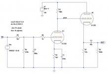
U101 is an inverting amplifier with adjustable gain. The output feeds into an overload indicator which is an opamp comparator with some digital logic to make an LED flash when a pre-adjusted voltage is exceeded. The FET J1 is where it all happens. The bias current is set by U2. Its non-linear current transfer function is converted to a voltage by U102 and U103. The distorted signal is than added to the normal one by U104.
The input stage is set by the Level control. Effect controls how much of the distorted waveform is added to the non-distorted one. Gain sets the output level. Pretty neat!
Check out the "Das Ist Aber Schade" thread in the Pass forum for a simple implementation of a single-ended amp using a mosfet with Schade feedback. Try here http://www.diyaudio.com/forums/pass-labs/215534-das-ist-aber-schade.html .
Last edited:
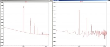
To find out just how similar the distortion is, I ran a SPICE simulation on a simple all valve circuit. The FFT of the Danyuk circuit output voltageis on the left and that of the plate voltage of valve U1 is on the right. Both signals are 1kHz with input voltages tweaked to give about 1% THD. The output voltages are very different but there is more than a passing resemblance. Perhaps not a very scientific comparison but I can't think of a better one right now.
Attachments
One thing to keep in mind is that small signal triode distortion is very circuit dependent. Many people achieve <0.01 % THD under small signal conditions.
So, what is one trying to emulate? Small signal triode distortion? DHT output tube distortion in SE amplifier?
So, what is one trying to emulate? Small signal triode distortion? DHT output tube distortion in SE amplifier?
Check out the "Das Ist Aber Schade" thread in the Pass forum for a simple implementation of a single-ended amp using a mosfet with Schade feedback.
Aha, a way to sample the joys of transformer distortion using solid state componentry. Thanks for that. I will look into it. 😀
If you look in the "DIY corner" at the "SS Tabor" page on my website you'll find info on HV transformer coupled solid state amplifiers using cascode connected MOSFETs with Schade feedback.
The last amp in the series has been in constant use since 2005. Makes great music and helps heat the house in winter...
Gary
The last amp in the series has been in constant use since 2005. Makes great music and helps heat the house in winter...
Gary
Yes indeed: here is an example of emulator utilizing a real triode as model:Wouldn't it be much simpler to use a Triode?
http://www.diyaudio.com/forums/solid-state/235115-new-hybrid-concept-c-vac.html
I suppose the Triode Emulator is an effect pedal for guitar. It does make sense, it would be difficult to squeeze a real tube plus PSU in a small box, and this one can run from batteries.
gives bad taste in mouth, like a tea with "popcorn flavour"In my travels on the information super highway, I came across this gem. It emulates a triode using silicon, with nary a piece of glass in sight.
I suppose the Triode Emulator is an effect pedal for guitar. It does make sense, it would be difficult to squeeze a real tube plus PSU in a small box, and this one can run from batteries.
Why would it be difficult to squeeze into a small box? Tubes are used in effects boxes all the time running off low voltage walk-warts. No bulky HV power supply is necessary when distortion is desired.
Wouldn't it be much simpler to use a Triode?
Are you serious?
That's basically single generic FET and a DC servo. Can be operated from a ludicrously low voltage, low current supply (e.g. a single 9V battery) and built with super cheap generic components.
Unlike when using that real triode of yours.
Last edited:
Any thoughts?
This looks more like an FX box.
Published by t_ca
The design for a low-noise amplifier is presented. The amplifier has a tube-like transfer characteristic and produces
harmonic distortion components that are similar to triode preamplifier.
Here, the emphasis is on "distortion components". These are desirable for a guitar amp, but for reproduction, you want to minimize distortion components. For that purpose, triodes are preferred since these produce fewer distortion components, and therefore require less correction.
Local NFB is the usual way to get triode-like behaviour from both pents and solid state by restoring the NFB that's inherent to the triode with its greater dependence of Ip on Vpk which every other device all but eliminates.
yes and there are dozens of types of tube distortion simulators in (cheaper) guitar amps but the best still use tubes. I also see little point in using this simulator to add distortion to a clean SS amp.
You need somewhere around 4 slightly different Schaded sand
triode emulators in parallel, to convincingly emulate a triode.
That said: It matters much less wether your Schaded sand is
MOSFET or BJT. BJT has less capacitance issues, so I lean in
that direction. I may be the only one...
Triode curves will come from unequal cutoff of your emulators.
The size of the set diminishes, and thus changes the average.
A completely normal behavior that happens in real triodes.
The diminishing set effect does not and will not ever happen in
Schaded sand with only one device with one uniform cutoff.
One device cutoff is too abrupt, and not like the real thing.
Last edited:
I'm a silicon guy, but that circuit is very interesting.
I got around this problem by boosting the output of an ECC88 to the level of 50 + watts
depending on B+ and transformer ratios.
I expect 115 to 120 db signal to noise in an amp and the only way to achieve that is with silicon. B+ voltage reg. , NPN concertina , mosfet output boost. DC heater
Tubes have a very pleasing sound
- Status
- Not open for further replies.
- Home
- Amplifiers
- Tubes / Valves
- Triode simulation/emulation with solid state