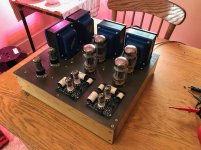
Hi All! I have built a few amp kits and worked on some guitar amps with success. For this build I wanted to venture just a bit farther from a kit and spec out the part / build the chassis myself.
The result is a single chassis that incorporates two Triode Electronics Dynaco Mk3 input board amps. No components are shared (except for the grounded frame).
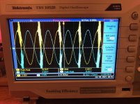
The amp sounds great and puts out the 60w RMS that it should. When I hooked it up to the scope to balance the phase inverter using RX1, probes on Pad 1 and Pad 3 to Pad 2a & 2b (as per instructions), the attached nasty distorted waveform resulted. If I keep the voltages roughly 10% off from being balanced, this distortion goes away. Increasing amp input (1khz test signal) makes it more likely to occur and requires further unbalance to make it go away.
If both channels are turned on, there is a very high pitched oscillation that can only be heard on my high efficiency horn speakers - messing with RX1 can make it go away if the phases are enough apart.
Would somebody be so kind as to send me down the right troubleshooting road? I am skilled in electronics, but am not highly experienced in audio circuits.
Thanks,
Pete
The result is a single chassis that incorporates two Triode Electronics Dynaco Mk3 input board amps. No components are shared (except for the grounded frame).
The amp sounds great and puts out the 60w RMS that it should. When I hooked it up to the scope to balance the phase inverter using RX1, probes on Pad 1 and Pad 3 to Pad 2a & 2b (as per instructions), the attached nasty distorted waveform resulted. If I keep the voltages roughly 10% off from being balanced, this distortion goes away. Increasing amp input (1khz test signal) makes it more likely to occur and requires further unbalance to make it go away.
If both channels are turned on, there is a very high pitched oscillation that can only be heard on my high efficiency horn speakers - messing with RX1 can make it go away if the phases are enough apart.
Would somebody be so kind as to send me down the right troubleshooting road? I am skilled in electronics, but am not highly experienced in audio circuits.
Thanks,
Pete
Attachments
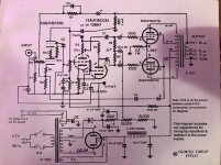
There is some kind of instability and oscillation. Double the value of C7 and see if the oscillation is still present.
Last edited:
Thanks, will order some more mica caps tomorrow morning. Any other parts that I should put in the order? I choose a whole variety of the pf level caps (c7,c4, c5). Have substitution boxes for the higher level ones.
Look to me it is spurious oscillation from too much NFB (likely OPT). I would reduce nfb by altering R8 and R9 ratio. Reduce R9 while keeping bias same. Keeping some margin so it won't oscillate with music contents.
Thanks! I'll give that a shot. I am running different transformers from what the kit would have offered. The impedances are the same however the manufacturer and wattage rating (mine are 100w) are different so that could be causing an issue.
Something that confuses me, the directions first talk about R7 as the feedback resistor, and that makes sense to me. Then they start to refer to R11 as the feedback resistor. That doesn't seem to be correct and might be a typo (of course I certainly could be wrong too).
Would it be possible to change R7 to vary NFB? It is a 1/2w rated resistor and I have a substitution box that could flip through increasing values easily while testing. I see how adjusting the R8/R9 ratio would also accomplish this, but would require two resistor changes per test to keep the bias the same and only vary the point where the NFB is inserted.
Thanks for bearing with my beginner-ish questions!
-- Pete
Increase R7 can reduce NFB from that FB path. You can try that first. There is another NFB path via C4. Changing R7 won't effect that if the problem is from there.
Thanks for the help. I just got back to the bench for some further tests. I do not have the proper combos of resisters to change the ratio of R8/R9, but do have some on order now. In the meantime, and hopefully an equivalent tests:
1) Removed the connection at eyelet 4, to the screen grid of the lower power tube. This connection is labeled PFB (positive feedback I assume). This had zero effect on the issue.
2) The above cleared the way for putting a parts substitution box where R7 was. 1.5k was the stock value and provided about 17dB of gain reduction measured on the scope at low outputs before the distortion kicked in.
3) Learned that decreasing NFB (by increasing R7) made the distortion kick in at lower signal tone values. Raising the NFB delayed the onset of distortion. By 500 ohms (stock 1.5k), it was starting to cause issues of it's own,
Conclusion, the NFB is helping to quell the distortion.
But here is where I am stuck... where might the distortion be originating from?
The only thing that seems to kill the oscillation and allow the volume to be increased is using RX1 to unbalance the phase inverter - it'll make rated power if the balance is off by 35%.
Last edited:
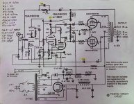
Try to add a zobel network on the output transformer, com to 16 ohm tap, a 10 to 15 ohm resistor series with a 0.068 to 0.1 uf cap.
Just a bit of a followup after applying some changes, in case anybody else finds themselves in the same situation someday.
1) Replacing the 10pf cap at C7 with 100pf (I worked my way up to this in 10pf increments) got rid of the oscillation and allowed R1x to balance the phase inverter without oscillation at anywhere between 20hz-20khz - and just below the onset of clipping.
2) The amp required excessive pre-amp amplitude to get to clipping, and "something" didn't seem quite right with the sound (though I couldn't find anything alarming with the scope and frequency generator). I ended up replacing R7 (feedback resistor) with a 3.3k resistor. This got me 5dbm more gain, but also lost 3dbm at 20khz. I am fine with that and the sound is more pleasing to my ear. Some of that may be due to my high efficiency horn speakers - the high frequency rolloff took a bit of harsh edge off.
Thanks to all of you that helped me out!
-- Pete
- Home
- Amplifiers
- Tubes / Valves
- Triode Elec. Dynaco Mk3 Distortion