Don't know what you mean by that...🙄
Yep. But...preferring not to have an input cap...leaves me with the low value of Rk to set the bias...right?
There is no way to bias the grid at 0v and at the same time use a resistor for the cathode. It must be ridiculously low, useless as a load.
Only with a -so called- anode choke you can have both: High AC load and low dc resistance.
You need something like 100 Henry with say 1KOhm dc res. to bias the cathode to about 4V (when we assume that you run e.g 4mA through the tube).
Last edited:
There is no way to bias the grid at 0v and at the same time use a resistor for the cathode. It must be ridiculously low, useless as a load.
Only with a -so called- anode choke you can have both: High AC load and low dc resistance.
You need something like 100 Henry with say 1KOhm dc res. to bias the cathode to about 4V (when we assume that you run e.g 4mA through the tube).
Sounds like the excellent Lundhal 270H chokes (1k2 DC).
Is the choke (that wants to keep the current as stable as possible) current-source enough be called a "current source"...or will it be merely an F-dependend induction with Rseries + L being a dynamic very high imp load helping the PSRR?
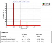
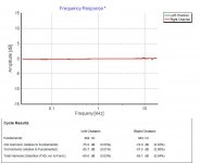
Results so far for the DAC + Tubes Channels build with "free assembly" not noise-free or matched parts yet:
What test equipment did you use to make those measurements?Results so far for the DAC + Tubes Channels build with "free assembly" not noise-free or matched parts yet:
Cheers
ian
What test equipment did you use to make those measurements?
Cheers
ian
Fancy, isn't it? 😀
Well, the actual measurements were done with regular equipment as a scope and a HP THD meter. The software you see I usually use for Azimuth alignment of my cartridge and I figured that if it had THD measurement and F-sweep...I could also use it for measuring the tube-stage+DAC...software is called Adjust+ by Dr. Chris Feickert...highly recommended!
- Status
- Not open for further replies.