Trimming DC offset/DC-servo and BTL TA2022
Well, I've gotten the TA2022 BTL amp built to a stage where it's time for trimming down the DC offset before putting each of the two boards in BTL mode.
I've got some questions on this...
Is the TA2022 able to run without load? Ie, can I trim down DC offset without a load connected?
Are my woofers ok with that DC offset until trimmed down?
I get about +89mVdc on the board I bought a few years ago assembled (when jumpered for BTL operation). DC offset spikes to over +350mVdc at power off.
All the above without load on inputs or outputs(I had the amp powered on for about 5sec as I didn't want to risk damage if the TA2022 doesn't like running without a load).
My woofers specs (the amp connects directly to the woofers as the crossover is active with dipole comp.)
I appreciate any and all help as this is the last steps before getting my main system up and running again.
TA2022 stereo mode - mid & treble, passive x-over
TA2022 BTL - Woofers, x-over and dipole comp via DCX2496
Well, I've gotten the TA2022 BTL amp built to a stage where it's time for trimming down the DC offset before putting each of the two boards in BTL mode.
I've got some questions on this...
Is the TA2022 able to run without load? Ie, can I trim down DC offset without a load connected?
Are my woofers ok with that DC offset until trimmed down?
I get about +89mVdc on the board I bought a few years ago assembled (when jumpered for BTL operation). DC offset spikes to over +350mVdc at power off.
All the above without load on inputs or outputs(I had the amp powered on for about 5sec as I didn't want to risk damage if the TA2022 doesn't like running without a load).
My woofers specs (the amp connects directly to the woofers as the crossover is active with dipole comp.)
Product Specifications
Nominal Diameter15"
Power Handling (RMS)350 Watts
Power Handling (max)700 Watts
Impedance8 ohms
Frequency Response20 to 500 Hz
Sensitivity88.2 dB 1W/1m
Voice Coil Diameter2"
Magnet Weight90 oz.
Thiele-Small Parameters
Resonant Frequency (Fs)21.5 Hz
DC Resistance (Re)5.2 ohms
Voice Coil Inductance (Le)3.08 mH
Mechanical Q (Qms)8.92
Electromagnetic Q (Qes)0.63
Total Q (Qts)0.59
Compliance Equivalent Volume (Vas)8.79 ft.³
Mechanical Compliance of Suspension (Cms)0.26 mm/N
BL Product (BL)15.46 Tm
Diaphragm Mass Inc. Airload (Mms)207g
Maximum Linear Excursion (Xmax)14.3 mm
Surface Area of Cone (Sd)819.4 cm²
I appreciate any and all help as this is the last steps before getting my main system up and running again.
TA2022 stereo mode - mid & treble, passive x-over
TA2022 BTL - Woofers, x-over and dipole comp via DCX2496
Last edited:
The spike in DC on power off is not that nice though...
I'm going to test the second board after today. I've swapped a resistor and the 7805. Keeping my fingers crossed there wasn't something else causing the problem(that made the 7805 and resistor start to smoke).
I'm going to test the second board after today. I've swapped a resistor and the 7805. Keeping my fingers crossed there wasn't something else causing the problem(that made the 7805 and resistor start to smoke).
Well, it's been a while and the two boards (populated) have been collecting dust until now.
Reasons are many, including moving to a bigger apartement and the birth of my daughter 2 months ago.
Anyway, I figured it might be better to use a DC-servo for "offset trimming" then to try to get it as close to zero as possible with the trimpots.
The TA2022 evaluationboard used DC-servo IIRC.
I have a design of an OPA2134 DC-servo that works very well in simulations.
Granted I have not done simulations with the TA2022 as I don't have the LTspice model. Simulations was made on other circuits I am working on.
Now, at long last, to my question:
How to "convert" LJM TA2022 boards to use DC-servos instead of the two 50K trimpots?
What to remove/add, where to hook up in/out of the DC-servo etc.
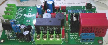
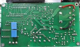
I don't have a schematic of this particular board unfortunately.
The attached pics are from when I populated the board. Please excuse quality of the pics and that the flux was not cleaned off.
Reasons are many, including moving to a bigger apartement and the birth of my daughter 2 months ago.
Anyway, I figured it might be better to use a DC-servo for "offset trimming" then to try to get it as close to zero as possible with the trimpots.
The TA2022 evaluationboard used DC-servo IIRC.
I have a design of an OPA2134 DC-servo that works very well in simulations.
Granted I have not done simulations with the TA2022 as I don't have the LTspice model. Simulations was made on other circuits I am working on.
Now, at long last, to my question:
How to "convert" LJM TA2022 boards to use DC-servos instead of the two 50K trimpots?
What to remove/add, where to hook up in/out of the DC-servo etc.
I don't have a schematic of this particular board unfortunately.
The attached pics are from when I populated the board. Please excuse quality of the pics and that the flux was not cleaned off.
Attachments
I did some measurements, in circuit, on two boards and got the following.
Pins are on the TA2022.
Pin30 is FBKGND1, pin28 is FBKGND2
Pot 1 is the one closest to the edge of the PCB. (That's just what I call them to keep track)
Board1
Pot 1 viper to pin30 3K35, to pin28 4K05
Pot 2 viper to pin30 4K06, to pin28 3K38
Board2
Pot 1 viper to pin30 3K41, to pin28 4K1
Pot 2 viper to pin30 4K12. to pin28 3K43
The resistor between viper and FBKGND's seem to be 5K7 (from the colorcode).
The datasheet suggests a 10K resistor in that spot.
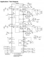
The trimpots connects to V5, FBKGND and AGND according to the datasheet suggested schematic(attached).
Pins are on the TA2022.
Pin30 is FBKGND1, pin28 is FBKGND2
Pot 1 is the one closest to the edge of the PCB. (That's just what I call them to keep track)
Board1
Pot 1 viper to pin30 3K35, to pin28 4K05
Pot 2 viper to pin30 4K06, to pin28 3K38
Board2
Pot 1 viper to pin30 3K41, to pin28 4K1
Pot 2 viper to pin30 4K12. to pin28 3K43
The resistor between viper and FBKGND's seem to be 5K7 (from the colorcode).
The datasheet suggests a 10K resistor in that spot.
The trimpots connects to V5, FBKGND and AGND according to the datasheet suggested schematic(attached).
Attachments
I've ordered the parts I didn't have at home to make DC-servo's as per the EV board schematic.
Should be able to figure where and how to hook that circuit to the TA2022 board from reading the schematic and measuring the boards.
Should be able to figure where and how to hook that circuit to the TA2022 board from reading the schematic and measuring the boards.
Personally I wouldn't be worrying about 89mV.
Till I know, Dc offset of about 30mV is the maximum acceptable.
Till I know, Dc offset of about 30mV is the maximum acceptable.
I'd like to get below that if possible.
The DC offset of the two, not in usel, boards is about 350mV for the one I've tested so far. Diy takes time now with a two month old baby girl in the house.
The thing is that I don't know if it's ok to keep the board powered on for any periods of time without any load. I don't want to risk my Dayton woofers, and I don't have anything like 25-50W 8R load-resistors...should really get some though...
- Status
- Not open for further replies.
- Home
- Amplifiers
- Class D
- Trimming DC offset and BTL TA2022