Hi guys,
Here’s a nightmare repair which seems not to have an end. To date, I’ve been struggling with this device for months.
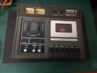
It’s Transylvania (?) Cassette Deck, Model GR-18,I think is dated somewhere between mid/late 70s not beyond early 80s, sure hasn't been used for a long time. Searching the web, I found out that Transylvania was part of Asahi Corp. further information are nowhere to be found. I only found a single picture of this model, and of course no schematics at all.
The problem is: dead left ch. I mean totally dead, no Rec., no Play, not even on the phones. The other channel is ok.
Things I already did:
1. Cleaned and demagnetized the heads
2. Thoroughly cleaned the rec/play multiple switch by disassembling it and cleaning every single contact.
4. Checked all the channel components on board and all the semiconductors also off board.
3. Replaced the Dolby IC, based on what someone said to be “common fault”
4. On Mooly’s suggestion I also verified continuity between the cables coming from the heads and their respective connection on the PCB.
I'm sure someone has already put his hands on it, the signal cable coming from that channel head was soldered on the same pad of the ground. So it could be the same thing for one or more of the many cables attached under the PCB.
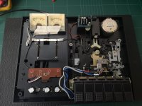
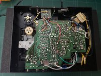
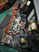
The problem with this unit is the top side of the PCB is hard to access, unless desoldering 20+ wires attached to random zones of the PCB itself (top & bottom side). Any move of the board can lead to wires disconnection, it actually happened several times, and you can go crazy finding out where they came from. Very bad design and construction: cable mess, no silkscreen etc.
All in all, quite a challenge for a hobbyist like myself. Hope you guys can help, thank you.
Here’s a nightmare repair which seems not to have an end. To date, I’ve been struggling with this device for months.
It’s Transylvania (?) Cassette Deck, Model GR-18,I think is dated somewhere between mid/late 70s not beyond early 80s, sure hasn't been used for a long time. Searching the web, I found out that Transylvania was part of Asahi Corp. further information are nowhere to be found. I only found a single picture of this model, and of course no schematics at all.
The problem is: dead left ch. I mean totally dead, no Rec., no Play, not even on the phones. The other channel is ok.
Things I already did:
1. Cleaned and demagnetized the heads
2. Thoroughly cleaned the rec/play multiple switch by disassembling it and cleaning every single contact.
4. Checked all the channel components on board and all the semiconductors also off board.
3. Replaced the Dolby IC, based on what someone said to be “common fault”
4. On Mooly’s suggestion I also verified continuity between the cables coming from the heads and their respective connection on the PCB.
I'm sure someone has already put his hands on it, the signal cable coming from that channel head was soldered on the same pad of the ground. So it could be the same thing for one or more of the many cables attached under the PCB.
The problem with this unit is the top side of the PCB is hard to access, unless desoldering 20+ wires attached to random zones of the PCB itself (top & bottom side). Any move of the board can lead to wires disconnection, it actually happened several times, and you can go crazy finding out where they came from. Very bad design and construction: cable mess, no silkscreen etc.
All in all, quite a challenge for a hobbyist like myself. Hope you guys can help, thank you.
Attachments

Just very quickly...
Firstly what is this:

And I was going to say if you desolder the white and red wires and put it into play mode and then touch the pads where the wires go then the meters should go nutz as you should get loads of hum and noise through stray pickup.
Firstly what is this:
And I was going to say if you desolder the white and red wires and put it into play mode and then touch the pads where the wires go then the meters should go nutz as you should get loads of hum and noise through stray pickup.
Use phone camera to take photos before doing any work on soldering etc., it is very handy when you are trying to work on the circuit, particularly without silk screen to guide you.
Are the motor and belts okay?
That can also be a problem nowadays though one channel okay means that for now no issue, you can always measure belt size for future requirement now.
Are the motor and belts okay?
That can also be a problem nowadays though one channel okay means that for now no issue, you can always measure belt size for future requirement now.
NaresBrd, Mooly, thanks for your replies.
I checked the heads for coil continuity and they are OK, slight difference in resistance value but I don't think is a problem, considering i didn't disconnect them. I also tried the other thing NareshBrd suggested: I fed the record input with an external audio (no cassette, just manually activated the tab-switch) and for the first time I heard both the channels!
Please consider that, when I tried to record a stereo source, the Left ch. recorded nothing.
@Mooly - Not sure to understand, red and white wires are from the right ch., the working one. The six PCB pads, L to R, are:
Left ch head (blue), Shield, Left head (grey),
Right ch. head (white), Shield, Right ch. head (red).
Shields and white/gray wires are connected (shorted).
@NareshBrd - Yes I took pics of everything before to begin. Belts are a bit loose but working, I'll measure them for possible future replacement.
Sorry, it's me misreading the pictures.Not sure to understand, red and white wires are from the right ch., the working one. The six PCB pads, L to R, are:
Disconnect the head to the faulty channel at the PCB and with the deck in play mode just 'buzz' the isolated pads and see if the meters respond. Its a really crude test but shows if there is signal gain and that at least something is getting through. Compare with the other channel if needed.
If you still have no signal then try and locate visually the transistors in each front end stage on a channel by channel basis and compare voltages on the transistors in each channel with the deck in play mode.
Spray all the switches with CRC 2-26 or equivalent contact cleaner, work them and leave overnight.
Chek next day...could be simply tarnished contacts in switches, and corrosion at wire joints.
Then start with bad electrolytic capacitors and so on, electronic issues.
Check supply volts to both channels, could be no supply to one channel...
Chek next day...could be simply tarnished contacts in switches, and corrosion at wire joints.
Then start with bad electrolytic capacitors and so on, electronic issues.
Check supply volts to both channels, could be no supply to one channel...
Thanks guys,
Well, I disconnected the left-head wiring on the PCB side and I was able to get some sound in the output, connected to a pair of amplified speakers.
I also tried to inject some signal directly on the PCB pad by using a rudimentary self-made buzz generator and I got sound on both channels. The left ch. being a lot weaker anyway, I'd say 50/60% off.
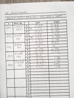
I also reported all the V+ values on the transistors leads and noticed that some differ a lot from left to right. I performed the test by attaching the black lead of the DMM on the ground and the red for testing.
What I found is reported on the attached table.
All the mechanical contacts have been cleaned and tested and are OK. I’d like to test all the electrolytic caps, but I just have a 10$, 2006 multimeter and a Chinese component tester which is quite approximate on caps testing.
By the way, none of them is bulged, and when I started working on this unit, I tested most of them off board with the Chinese tester and they appeared to be OK.
I will upgrade my lab in the next but I’m on a budget, so for now I just ordered a 3 in 1 Multimeter, Scope and AWG (OWON HDS242S) which hopefully will allow me better measurements. If I succeed in this repair hobby, sure I will invest more in tools and equipment.
PS: I found out that the PCB actually has the silkscreen, it was hard to see cause the PCB's top side was close to the chassis. More, the components practically cover the text.
Well, I disconnected the left-head wiring on the PCB side and I was able to get some sound in the output, connected to a pair of amplified speakers.
I also tried to inject some signal directly on the PCB pad by using a rudimentary self-made buzz generator and I got sound on both channels. The left ch. being a lot weaker anyway, I'd say 50/60% off.
I also reported all the V+ values on the transistors leads and noticed that some differ a lot from left to right. I performed the test by attaching the black lead of the DMM on the ground and the red for testing.
What I found is reported on the attached table.
All the mechanical contacts have been cleaned and tested and are OK. I’d like to test all the electrolytic caps, but I just have a 10$, 2006 multimeter and a Chinese component tester which is quite approximate on caps testing.
By the way, none of them is bulged, and when I started working on this unit, I tested most of them off board with the Chinese tester and they appeared to be OK.
I will upgrade my lab in the next but I’m on a budget, so for now I just ordered a 3 in 1 Multimeter, Scope and AWG (OWON HDS242S) which hopefully will allow me better measurements. If I succeed in this repair hobby, sure I will invest more in tools and equipment.
PS: I found out that the PCB actually has the silkscreen, it was hard to see cause the PCB's top side was close to the chassis. More, the components practically cover the text.
Attachments
Those readings point to a problem... I have recollection that the 2SC458 transistor is notorious for something called 'Hitachi rot'.
Do the legs of those transistors look black or purple/black as if corroded?
Without a circuit to do proper fault finding I think it might be worth just changing them. I would maybe suggest BC549C (different pin out but no problem in practice if you gently form the leads)
https://www.farnell.com/datasheets/727135.pdf
A small-signal transistor with matching and similar characteristics pinout shouldn't be that exotic either though... KSC1845 and the like. BC549C/BC550C would, however, probably be closer process wise.
Yeah..... Those are most likely the culprits.Those readings point to a problem... I have recollection that the 2SC458 transistor is notorious for something called 'Hitachi rot'.
Do the legs of those transistors look black or purple/black as if corroded?
Without a circuit to do proper fault finding I think it might be worth just changing them. I would maybe suggest BC549C (different pin out but no problem in practice if you gently form the leads)
https://www.farnell.com/datasheets/727135.pdf
A rule of thumb when working on that age of equipment, especially Akai´s:
See a 2SC458?? Replace ASAP..... Then go on ........ 😉
And YES....... their legs are all black in 2025.
Just a word of caution: the earliest 2SC458s (angular case) had their pinout reversed compared to the later ones (in the standard TO-92 case). I found this out the hard way when repairing my Denon turntable (which was chock full of these horrible Hitachi transistors with slowly corroding leads).A small-signal transistor with matching and similar characteristics pinout shouldn't be that exotic either though... KSC1845 and the like. BC549C/BC550C would, however, probably be closer process wise.
Thanks guys,
@Mooly: actually all the transistors (and switches) terminals are black-ish or dark, including the ones on the working channel. but it looks like superficial oxidation, not corrosion. Could that indicate an internal damage too?
Two questions, just to understand better:
1. Why don’t replace the 2SC458 with the same type?
2. What about the first transistor, the C1335? The value on the collector differs a lot from the corresponding tr. in the right channel. Doesn’t it look suspect?
PS: The list in my table is from the closest to the farther with respect to the heads. (C1335 the closest , last C458 the farthest).
PPS: The 2SC458s are in TO-92 package
Thank you
The well known problem with 2SC458 is the poor housing.Could that indicate an internal damage too?
The oxidation works its way through the pins into the housing and eventually destroys the transistor chip.
Because they have been obsolete for decades, and your chance of getting "fakes" is 99.9%.1. Why don’t replace the 2SC458 with the same type?
Also...... If you manage to get originals, being in a drawer for more than 40 years, they´ve probably gone bad too.
Since it´s no big cost, just replace all 8.What about the first transistor, the C1335? The value on the collector differs a lot from the corresponding tr. in the right channel. Doesn’t it look suspect?
I´ve seen people replace the 458 with 2SC2240 and were quite happy.
Just search the internet for "Hitachi rot 2SC458", and you´ll get plenty of stories....... and possible replacements 😉
Thanks for your quick reply, Boydk,
Yes, all that said, I think I will replace all the transistors. Of course I’ll have to do the same on both channels, starting with the faulty one.
It’s 5 transistors per channel:
• C458 (x3)
I've been suggested to replace them with BC549C/BC550C or 2SC2240. I also tried to make a search myself (all transistors.com), but I didn’t found any of the suggested replacements in their equivalent list.
• C1335 (x1)
• A844 (x1)
Tried to make a search but I got a ton of results. Are they displayed in order of relevance? Dealing with vintage audio, I think I will have to face this problem almost every time. Also looked for books, but I only found old editions (from about 1970 to 1980), so I guess they are useless, since equivalents will be obsolete as the original ones. Any suggestion to understand/learn about this subject?
These are long out of production and you may end up with either fakes or old stock with the same problems. Also never buy transistors and the like from eBay, always buy from authorised distributers.Why don’t replace the 2SC458 with the same type?
Not necasserily. The amplifier stage run with DC as well as AC feedback and it means a problem anywhere will throw all the voltage off.What about the first transistor, the C1335? The value on the collector differs a lot from the corresponding tr. in the right channel. Doesn’t it look suspect?
Companies like Farnell have these:
https://uk.farnell.com/multicomp-pro/bc549c/transistor-npn-30v-to-92/dp/1574382
or the Onsemi brand:
https://uk.farnell.com/on-semiconductor/bc549cta/transistor-bipol-npn-30v-to-92/dp/2453797
The BC559C is the PNP complement:
https://uk.farnell.com/on-semiconductor/bc559cta/transistor-bipol-pnp-30v-to-92/dp/2453808
Look at the data sheet for the pinouts.
There is no quick way to learn I'm afraid 🙂 You need to first understand the circuit theory and the operating conditions of the transistors and the parameters that really matter for that application to begin to come up with generic modern day replacements. Data books which were so valuable years ago have been replaced by online sites listing all of these devices and more.Also looked for books, but I only found old editions (from about 1970 to 1980), so I guess they are useless, since equivalents will be obsolete as the original ones. Any suggestion to understand/learn about this subject?
Use the simplest and easiest (low noise) you can get.
BC550C will do it for both the C458 and C1335.
BC560C will do it for the A844.
Remember to manipulate the legs/pins to the correct position.
+ It will be lower noise than before.
- You might have to recalibrate it on the electric side to get recording level/playback level to spec. and readjust VU-meter circuit.
We are talking fine tuning. The unit will work from startup (assuming the transistors really are at fault) 😉
@Mooly - Thank you for the explanation. Yes, I know you have to understand circuit theory first, and that’s what I’m learning now in tiny little steps (amps types and functioning, switching power supply, preamps etc.). At this moment I have basic knowledge of how components work but very little about the circuitry. I also know the basic laws (Ohm, Kirchhoff, Thevenin). The Scott repair has been quite a lesson for that, mostly thanks to the schematics and your indications. In the case of this cassette deck is really hard cause I don’t have the schematics and the layout is very confusing.
PS I only buy from qualified sellers (professional local stores or renowned websites such as TME, RS-Components, Digikey, Mouser, Reichelt).
@Boydk - Thanks for your suggestion, though I think I will go with the ones Mooly suggested (BC549C; BC559) cause I found them at a local store, so I can go take them and try.
Are the ones you advised a considerably better replacement? I could order them as well.
Probably not better. BC550 has a higher voltage rating (45v) than 549 (30v)
Just had a feeling, that they were easier to get, that´s all.
Just had a feeling, that they were easier to get, that´s all.
Hi guys,
a little update about this neverending repair. I replaced all the transistors with the alternatives Mooly suggested, leaving out just the C1335. Nothing changed. I tested the C1335 off board and the tester says it's ok.
I also did the buzz test again, disconnecting the head cable and touching the pad on the PCB, and I could hear the buzz as in the previous test.
Just to definitely rule out the heads from the suspects list, I inverted their connections on the PCB, nothing changed, that left channel is dead.
That said, if I put the unit in record mode and inject some audio signal into the RCA inputs, it works fine (I did this test days ago, and reported in one of my previous messages). So I think the problem is somewhere else. I'm afraid somebody messed up things before me (I initially found the signal wire from the head soldered to the ground pad).
With lots of wires going onto PCB (top & bottom), there's a lot of room for messing things up. If that is the case, it would be impossible to fix the deck without a schematics.
The fact is: you can't hear nothing, not even a basic output noise, nothing at all, like if the signal was shorted to ground before to reach the output jacks. The VU Meter doesn't move, not even at the startup (the other one does).
- Home
- Source & Line
- Analogue Source
- Transylvania GR-18 Cassette Deck. Left ch. dead