...yeah, I second that...around here Juma is a big brand...
😀
...though I'd prefer to put it like this ---> JumA, indicative of top-class A...
🙂
😀
...though I'd prefer to put it like this ---> JumA, indicative of top-class A...
🙂
@ Sir Juma:
Couple of quick questions...
Can I use two 22V/5A switching supplies (with fine adjustment of output voltage) with floating outputs for trying out #1?
Second, do I need to use two separate xformer windings/bridge rectifiers, or can a normal +/- lab supply be used ?
Couple of quick questions...
Can I use two 22V/5A switching supplies (with fine adjustment of output voltage) with floating outputs for trying out #1?
Second, do I need to use two separate xformer windings/bridge rectifiers, or can a normal +/- lab supply be used ?
You need two indipendent power supplies ie. two secondaries per channel.
Please read carefully the WHOLE post #1.
Please read carefully the WHOLE post #1.
Thank you sir.
Not that I did not read the intro fully... 😉
Two independent switching psu's with earth isolation usable ?
Not that I did not read the intro fully... 😉
Two independent switching psu's with earth isolation usable ?
exactly as per schematic
A quick (!) build...
Attachments
Thanks Juma!
I really like this one. Simple, super symmetric schematic.
Simple construction. Less is more 😀
I have 3 way speakers, my preamp can drive it, I have the laterals from Jacco and dual mono is preferred anyway.
I really like this one. Simple, super symmetric schematic.
Simple construction. Less is more 😀
I have 3 way speakers, my preamp can drive it, I have the laterals from Jacco and dual mono is preferred anyway.
My build
A note on my build:
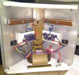
This is one design that proves less is more! And soldering all components onto the LatMOS pins and mounting it on the heatsink is a breeze. I have found that using a section of aluminium angle and two screws to clamp the device to the heatsink is far more effective than a simple screw and washer. Of course, you may use a smear of heatsink compound on BOTH sides of the device, as some heat is radiated by the clamp also.
Again, I have opted to use a set of parallel electrolytics instead of one big capacitor, which is measurably and audibly better, IMHO. In the final build I am using 9 numbers of 3,300 uF capacitors, plus one non-polar 4 uF.
The R-core supplier had only 12 V and 24 V units in stock and I got the less expensive 12 V units for tests. They have a 16V/5A unit, but because of covid restrictions, it will be delayed by a few weeks. I have biased the amp at around 500 mA (16 VDC rails)as advised by the master. The 20-22 VDC rails could use about 700 mA bias, beyond which either supply voltage or bias will have little effect, according to the designer.
R3/R7 is a combo of 15k and a 10k multiturn pot. The offset stabilizes after a few minutes and it is easy to bring it very close to zero, which stays there after a few hours of playing music. My heatsinks, about 12 inches tall, are just warm at 16VDC/500 mA.
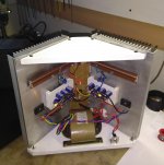
Opting for taller heatsink sections is a better bet, especially for class A amps. My "one heatsink per device" triangular layout is a carryover from one of my 'hot' amps from my college days in the 1970s. In the final build the bottom plate will be a plank of solid wood and the top plate acrylic. A perforated steel sheet will be above the transformer offering some shielding. So much for the cosmetics.
Hearing is believing, and all thanks goes to our dear Juma for his original designs!
A quick (!) build...
A note on my build:
This is one design that proves less is more! And soldering all components onto the LatMOS pins and mounting it on the heatsink is a breeze. I have found that using a section of aluminium angle and two screws to clamp the device to the heatsink is far more effective than a simple screw and washer. Of course, you may use a smear of heatsink compound on BOTH sides of the device, as some heat is radiated by the clamp also.
Again, I have opted to use a set of parallel electrolytics instead of one big capacitor, which is measurably and audibly better, IMHO. In the final build I am using 9 numbers of 3,300 uF capacitors, plus one non-polar 4 uF.
The R-core supplier had only 12 V and 24 V units in stock and I got the less expensive 12 V units for tests. They have a 16V/5A unit, but because of covid restrictions, it will be delayed by a few weeks. I have biased the amp at around 500 mA (16 VDC rails)as advised by the master. The 20-22 VDC rails could use about 700 mA bias, beyond which either supply voltage or bias will have little effect, according to the designer.
R3/R7 is a combo of 15k and a 10k multiturn pot. The offset stabilizes after a few minutes and it is easy to bring it very close to zero, which stays there after a few hours of playing music. My heatsinks, about 12 inches tall, are just warm at 16VDC/500 mA.
Opting for taller heatsink sections is a better bet, especially for class A amps. My "one heatsink per device" triangular layout is a carryover from one of my 'hot' amps from my college days in the 1970s. In the final build the bottom plate will be a plank of solid wood and the top plate acrylic. A perforated steel sheet will be above the transformer offering some shielding. So much for the cosmetics.
Hearing is believing, and all thanks goes to our dear Juma for his original designs!

Nice build Prof 
If you mount PSU closer to the bottom of the heatsink you'll manage to put MOSFETs in lower half of the heatsink (say 5 inches from the bottom) and the heat transfer will work better so you can put both MOSFETs on one heatsink (your construction should be sufficient to support the stereo version).
You shouldn't worry about the transformers - good R-cores are low radiation devices with no need for steel sheet shielding.
Thank you, dear Juma.
Noted the suggestions.
However, I feel I shall stick with the dual mono format for the moment. You need to have hot heatsink stacks, or really cool ones in a class A amp to impress the younger set...
;-)
Noted the suggestions.
However, I feel I shall stick with the dual mono format for the moment. You need to have hot heatsink stacks, or really cool ones in a class A amp to impress the younger set...
;-)
For some reason, I missed this thread for some time. But as soon as I discovered it, and being me a "Juma follower" the proto (with components on hand) was ready in a couple of hour. No problem to drive it with some of my preamp, but I wanted something less problematic by input impedance point of view, thus the schematic of #10 has been my choice. Based on a JFET pair of 10,75mA, the values of components of LSK pre (supply +/- 33v, that I "casually" had on hand) were acceptable. My batch of LatFETs with 3v of blue LED develops 600mA, perfectly manageable by thermal point of view.
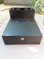
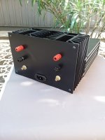
After some mechanical work, and based on excellent case from HiFi2000 plus two old heat sinks, the "Black Beauty" was born.
As you underlined, perfectly silent, easy to build and very stable. Excellent frequency response, and sound really convincing (it's currently driving a revised version of Altec Voice of the Theatre).
Gain is 20dB (10v/v), max output 18-20W per channel.
Juma, a couple of question: I'm using 220Ohm from pot's wiper to ground, and 2,2k // 10pF in the FB loop, do you deem they correct? or 120 and 1,2k would have any advantage? Resistor from LED's anode to ground is 3,9k.
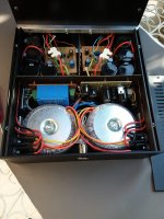
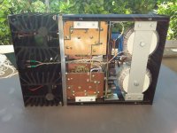
Some pics. The beauty of HiFi2000 case is that you can secure all components and PCBs to the sides, having access from above and below,
Many thanks again Juma, jour works are always inspiring
Guido
After some mechanical work, and based on excellent case from HiFi2000 plus two old heat sinks, the "Black Beauty" was born.
As you underlined, perfectly silent, easy to build and very stable. Excellent frequency response, and sound really convincing (it's currently driving a revised version of Altec Voice of the Theatre).
Gain is 20dB (10v/v), max output 18-20W per channel.
Juma, a couple of question: I'm using 220Ohm from pot's wiper to ground, and 2,2k // 10pF in the FB loop, do you deem they correct? or 120 and 1,2k would have any advantage? Resistor from LED's anode to ground is 3,9k.
Some pics. The beauty of HiFi2000 case is that you can secure all components and PCBs to the sides, having access from above and below,
Many thanks again Juma, jour works are always inspiring
Guido
Attachments


Last edited:
Hi Guido
I think you did a fine job
You can try following changes:
DC offset pot should be 20R - from pot's wiper to Gnd. - > 10R ; FB 100 - 200 R || 470 - 220pF
Gain stage real load (yours 3k9 from LED to Gnd.) can go up to 100k. Changing it manipulates THD especially H2.
Experiment and listen
I think you did a fine job
You can try following changes:
DC offset pot should be 20R - from pot's wiper to Gnd. - > 10R ; FB 100 - 200 R || 470 - 220pF
Gain stage real load (yours 3k9 from LED to Gnd.) can go up to 100k. Changing it manipulates THD especially H2.
Experiment and listen
How i missed this thread from the beguining?
Again, ORIGINAL design from ing. Juma
Thanks 🙂 Sipi
...
Nice works from GudoR and others who made this amp 🙂
Again, ORIGINAL design from ing. Juma
Thanks 🙂 Sipi
...
Nice works from GudoR and others who made this amp 🙂
@GuidoR
Excellent build that suits the amp and its spirit, IMHO!
Too bad I couldn't try the #10 version as good BJTs are unobtanium for me now...not that I didn't try!
I regularly use my #1 build--which has been borrowed now by a younger friend with better ears, and he is not returning it...
I use it with an OB; thinking of building a Frugel horn with Mark Audio MS-11. What do you think, sir?
Like you put it, a lot of us are Juma-followers!
Salutes to the master...and eagerly waiting for more inspired projects from him!
Hi Prof,
I think that you mean JFET, rather than the (very common) BJTs.
Contact me by private email, I may have some spares...🙂
I think that you mean JFET, rather than the (very common) BJTs.
Contact me by private email, I may have some spares...🙂
@ GuidoR:
... big oops! slip of the finger...JFET, it is!
Thank you, you are very kind...
I guess I would wait for a while until I could get some assured supplies of genuine stuff in enough numbers. Meanwhile I shall listen to the #1 version and concentrate on suitable DIY speakers. Here I would like your inputs as regards your experience with matching speakers, and also your take on the Mark Audio MS-11 as a possible candidate.
Thank you again, Sir.
- Home
- Amplifiers
- Pass Labs
- Transnova-Schade OS/Amp