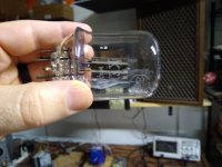
That's a beautiful tube.
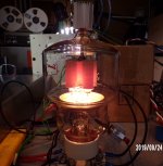
I got to testing these 826s a bit this weekend and I got very consistent results between the two samples I successfully tested. I didn't see any gas clouds. However, I would say that I was getting a little less current than I would expect from the datasheet. I'm guessing since I was running the grid at +15 and there is no datasheet curve for +15, but I think my combined plate and grid current should have been maybe 25% more. I got 72-73mA combined current @ 580V with +15 on the grid. Seems like I should have gotten more like 90.
Unfortunately, a third sample did not make it to the plate current phase of the test. I inserted it into the socket and heard some very quiet stress sounds from the glass (and thought, "that can't be good"). I fired it up anyway and got a puff of smoke from the filament and I knew I was done. I went to pull the tube from the socket and the whole top of the glass just came off from the bottom part with the pins.
Seller is replacing that one and another one that ejected pieces of the grid and filament all over the inside on its way to me.
Attachments

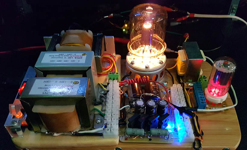
I got tube replacements for the bad ones.
One was gassy. The filament let off a cloud of smoke when I lit it up.
I assume this means that the tube is so gassy there is no bringing it back. Is that a correct assumption?
One was gassy. The filament let off a cloud of smoke when I lit it up.
I assume this means that the tube is so gassy there is no bringing it back. Is that a correct assumption?
It means the tube has air in it because of faulty seals. Remember I told you that many of these are like this. That's why I never bother with them.The filament let off a cloud of smoke when I lit it up. I assume this means that the tube is so gassy there is no bringing it back. Is that a correct assumption?
It means the tube has air in it because of faulty seals. Remember I told you that many of these are like this. That's why I never bother with them.
Yeah, I ordered from a vendor that stands behind their product, so they are sending replacements for bad tubes. But out of the 4 I ordered, 2 were bad (1 damaged in shipment). Out of the 2 replacements, 1 is bad. I'm not having great luck with the tubes from the vendor, but they are replacing them.
I took a chance on two really cheap ones on Ebay and both were good.
It's kind of fun, like gambling.
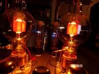
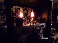
no getter triodes lik 100TH 250TL 304TL etc etc
need one week heather only wen start from old stock
need one week heather only wen start from old stock
Attachments
Last edited:
The 826 datasheet clearly says "forced air cooling" - normally this would be from below to keep the pin seal area coolest (differential expansion of pins w.r.t. glass is bad news, 200C is commonly quoted max temperature for pin/glass seals to prevent cracking/air ingress).
The 826 is rather inefficient for a transmitting tube needing 30W heater input for 60W max plate dissipation - this means its really hot even when doing nothing, so I'd take that forced-air cooling requirement seriously.
Other transmitter tubes use anode fins, allowing smaller internal dimensions for the same anode dissipation, and thus less heater power compared to plate power. For instance the QQV06-40 dual tetrode needs 2 x 5.5W heater for 2 x 20W plate dissipation - this tube can be operated without forced air cooling at lower power levels for instance.
Modern transmitting tubes use water-cooled anodes, which is a quiet(*) and reliable method of cooling - you ocassionally see some second hand that aren't in the stupidly high power range. The anode for these is more 'block' than 'plate'. There are examples of the 4CX250B that are water cooled for instance.
(*) The really big ones flash water to steam in the anode block to be able to handle megawatts of cooling, that won't be so quiet!
I think this might be the place to ask, I got a pair of 1970 vintage GM70 coming in through the mail, and i am wondering if anyone can recall the gettering modes of this particular model of tube? I am asking in relation to the burn in procedure.
The 826 datasheet clearly says "forced air cooling" - normally this would be from below to keep the pin seal area coolest (differential expansion of pins w.r.t. glass is bad news, 200C is commonly quoted max temperature for pin/glass seals to prevent cracking/air ingress).
The 826 is rather inefficient for a transmitting tube needing 30W heater input for 60W max plate dissipation - this means its really hot even when doing nothing, so I'd take that forced-air cooling requirement seriously.
I've been giving this a lot of thought. It looks like there are sockets out there to make this easy. Unfortunately, I don't have those. I have the square ceramic kind. I'm looking at it, though, and it looks like I could just make the hole big enough for air to pass around the bottom of the tube and space the socked downward below the chassis to make a path for air to flow.
I'm thinking I can strike a good balance between airflow and fan noise with some extra-quiet PC fans run at less than full speed.
The Heathkit SB-220 amplifier cooled two 3-500Z's with a pretty small fan.
It was mounted with the airflow split above and below the chassis.
This cooled the socket/pins and the envelope simultaneously.
It was mounted with the airflow split above and below the chassis.
This cooled the socket/pins and the envelope simultaneously.
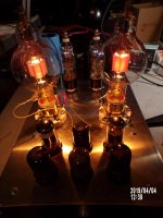
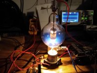
Well, I could use some advice on this guy (100TH). I'm getting a nice gas cloud when I start to apply any plate voltage. This is less than 100V on the plate with grid grounded. Current rises very quickly.
The other one I got has no gas cloud and I only get 6-7mA with over 500V on the plate.
Tube seller guarantees their tubes to meet manufacturer's specs. Should I try to heal it or should I exchange for another?
The other one I got has no gas cloud and I only get 6-7mA with over 500V on the plate.
Tube seller guarantees their tubes to meet manufacturer's specs. Should I try to heal it or should I exchange for another?
Attachments
I don't have a recommendation but thought you might be interested in the following.
The first linked page is from a HAM and mentions that an arc can clear the gas.
The section on Gettering and Arcing.
Then in the Eimac bulletin they refer to another procedure for high voltage conditioning.
Vacuum power tubes, using old valves, and vacuum tube failures
https://www.cpii.com/docs/related/22/AB21.pdf
As a kid, I went to the local 250 Watt AM radio station.
They had Red Plate Eimac tubes in the transmitter.
I never forgot that visit.
HollowState,
I finally looked at this thread, and at your tag line . . .
I think you let the cat out of the bag, but I am not sure (is it in there or not?).
They had Red Plate Eimac tubes in the transmitter.
I never forgot that visit.
HollowState,
I finally looked at this thread, and at your tag line . . .
I think you let the cat out of the bag, but I am not sure (is it in there or not?).
Last edited:
I agree with the above. Send that 100TH back. Heinz & Kaufman didn't make a good tube and you should avoid them. Stick with Eimac for the best chance of survival.
6A3sUMMER: I don't quite follow you. Or are you speaking of Schrödinger's cat which may or may not be alive? 🙂 🙁
6A3sUMMER: I don't quite follow you. Or are you speaking of Schrödinger's cat which may or may not be alive? 🙂 🙁
HollowState,
I am sorry for the diversion.
Yes, I referred to Schrodinger's observation, but I twisted it.
On top of that, there was the Pun, cat out of the bag (intended).
I combined that with Dr. Richard P. Feynman's lecture about electrons (or other particles?) headed towards a set of holes in a target.
I guess my thought was that with a politician, you can be certain that sooner or later, they will pervert things.
In my dictionary,
def: Politician, n. 1. A person who perverts things. 2. . . .
That is just my optimistic viewpoint.
Last edited:
Ok, I'll finish testing the other one that doesn't have a gas cloud and I'll work on sending that one back.
The other one with no gas cloud is an Eimac tube.
The other one with no gas cloud is an Eimac tube.
What are you doing with the grid for this 6-7 mA?The other one I got has no gas cloud and I only get 6-7mA with over 500V on the plate.
If you connect grid to plate (making a diode) and put 100 volts across the tube you should pull around 450 mA. If it's much less then this, it's probably weak. Then drop the filament by 10% and see if plate current sags much. (This figure is from my list of several dozen transmitting tube 100V simple emission tests)
- Home
- Amplifiers
- Tubes / Valves
- Transmitter Tube Testing