Lets face it, big tubes look really, REALLY cool (even though they are red hot) when they are running and sitting on top of an amp!
Unfortunately, they are ungodly to drive (depending on how big) and provide outputs that require AC transmission line sized transformers to be made useful, and among other things dont have very suitable characteristics for audio use in general...
But this got me thinking! There must be a way to make it work! - And not just work, work nicely and provide beautiful sound.
So first thoughts of course were to try and do it the normal method, and just construct a welding-spec power supply and have a super massive OPT - Obviously though this would realistically be unfeasible.
So how about OTL??? Although not the obvious choice it is more achievable I think. Simply going the old school route of running many tubes in parallel is not ideal because the amp would function more or less as a low efficiency 4 kilo watt room heater so another method must be taken.
Circlotron maybe?! Sounds promising at first but again doing this set up with tubes would require many stages to provide a useable output and many tubes all adding distortion etc... - not ideal.
So this leave me with my final (and better so far I think) idea to have a minimal voltage gain stage using a single transmitter tube running class A full time (or maybe push pull?) followed by a solid state mosfet current gain stage (also running class A).
Thoughts on this so far;
- The tube gain stage can happily run in class A full time and at low efficiency as they are high output devices so give plenty of headroom for what is being asked of them.
- It is possible to set up a circlotron output stage using MOSFETs also, not sure on this though because of the power supply requirements and also differential input ect ect
Specifications -
Would ideally like to have ~20 watt output (per channel into 8 Ohms)
Would like to have as few gain stages as possible as to have THD as low as possible (super super low)
Wanting to have super low THD brings up the issue of which config to run?
So thats what i'm asking - any ideas are helpfull - So far im leaning towards a more single design as i wish to use this as a headphone amp aswell (with lower gain of course!!) and single ended will make this easier.
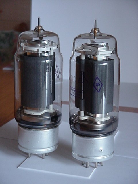
Pictures below graphically demonstrating the sexyness of large tubes

Unfortunately, they are ungodly to drive (depending on how big) and provide outputs that require AC transmission line sized transformers to be made useful, and among other things dont have very suitable characteristics for audio use in general...
But this got me thinking! There must be a way to make it work! - And not just work, work nicely and provide beautiful sound.
So first thoughts of course were to try and do it the normal method, and just construct a welding-spec power supply and have a super massive OPT - Obviously though this would realistically be unfeasible.
So how about OTL??? Although not the obvious choice it is more achievable I think. Simply going the old school route of running many tubes in parallel is not ideal because the amp would function more or less as a low efficiency 4 kilo watt room heater so another method must be taken.
Circlotron maybe?! Sounds promising at first but again doing this set up with tubes would require many stages to provide a useable output and many tubes all adding distortion etc... - not ideal.
So this leave me with my final (and better so far I think) idea to have a minimal voltage gain stage using a single transmitter tube running class A full time (or maybe push pull?) followed by a solid state mosfet current gain stage (also running class A).
Thoughts on this so far;
- The tube gain stage can happily run in class A full time and at low efficiency as they are high output devices so give plenty of headroom for what is being asked of them.
- It is possible to set up a circlotron output stage using MOSFETs also, not sure on this though because of the power supply requirements and also differential input ect ect
Specifications -
Would ideally like to have ~20 watt output (per channel into 8 Ohms)
Would like to have as few gain stages as possible as to have THD as low as possible (super super low)
Wanting to have super low THD brings up the issue of which config to run?
So thats what i'm asking - any ideas are helpfull - So far im leaning towards a more single design as i wish to use this as a headphone amp aswell (with lower gain of course!!) and single ended will make this easier.
Pictures below graphically demonstrating the sexyness of large tubes
An externally hosted image should be here but it was not working when we last tested it.
Few gain stages normally guarantees high THD, as there is insufficient gain for any feedback and decent amounts of feedback are the way to get "super super low" THD. I make no comment on whether "super super low" THD is a desirable aim in itself.Would like to have as few gain stages as possible as to have THD as low as possible (super super low)
Personally, I would rather see a transmitter valve in a transmitter doing what it was designed to do rather than just being a piece of audiophile jewelery.
Thanks for the reply!
Yea sorry forgot to mention that hopefully with using a transmitter tube you will be able to run with high enough gain (because it has alot of headroom) to be able to run a decent amount of negative feedback and then still have plenty of gain left over for the solid state stage.
I will hopefully experiment and see what sounds the best in my ears (that's what really matters at the end of the day right?) but for the time I would like to head in the direction of low THD.
I guess it would probably be smarter to go for push pull in both stages I guess to get lower distortion and tbh, I dont mind the idea of having both input and output as differential (no phase splitters) even though this means there will have to be a phase splitter upstream of the amp if i'm not using a balanced source device.
Any thoughts would be much appreciated!
Thanks again!
Thanks for the reply!
Yea sorry forgot to mention that hopefully with using a transmitter tube you will be able to run with high enough gain (because it has alot of headroom) to be able to run a decent amount of negative feedback and then still have plenty of gain left over for the solid state stage.
I will hopefully experiment and see what sounds the best in my ears (that's what really matters at the end of the day right?) but for the time I would like to head in the direction of low THD.
I guess it would probably be smarter to go for push pull in both stages I guess to get lower distortion and tbh, I dont mind the idea of having both input and output as differential (no phase splitters) even though this means there will have to be a phase splitter upstream of the amp if i'm not using a balanced source device.
Any thoughts would be much appreciated!
Thanks again!
Hi ,
the most of transmitter tubes are also designed to use in audio applications, but not in that way as you like. Unless you are in need of an 5 kilowatt amp to blow your neighbourhood up.
If you want to employ a transmitter tube which is designed to operate on 2500V plate on say 300V they would perform bad.
If you need only 20-30 watts choose tubes which are designed to this power level.
Yes there where some guys which build single ended 50W amps with huge transmitting tubes . But there are only few types of tubes which are suitable for this and the guys are quite seasoned in their business. And on the other hand they didn´t told us how many transformers they have rewound, how many tubes are blown and how many times they fiddled about their driver circuits before their development was an acceptable result . These guys are freaks , they like to do so and never care about the waisted money.
And so the financial point is also subject to reconsider before you start to bulid such an amp.
If you are new in tube diy start simple objects to gain experience . One day you will realize that a project which seem simple in the beginning are impossible to realize the more you think about it.
I also like huge transmitting tubes but I really can hold myself back to start such an Intension.
73
Wolfgang
Personally, I would rather see a transmitter valve in a transmitter doing what it was designed to do rather than just being a piece of audiophile jewelery.
I don't agree 🙂 jewlery is for adornment which implies absence of function. Also if you need high power levels and either do not want to go SS or venture into PPP territory then high power tubes are the only solution.
🙂
Apparently only 20 watts required; so a big transmitter valve would/ must have an element of jewelry about it.
I make no secret of my love of these devices. On the other hand for 20W it does seem a lot of trouble. There will be plenty of distortion in a SE amplifier; push-pull adds greatly to the cost of course with big valves.
I built a p-p amplifier using triode-strapped 813s; it made about 40W and sounded very nice. 813 as a triode is easy to drive: at 850V and 100mA bias was -75V. But oh my! the cost...
He could get an easy 30W at low voltage using triode-strapped 13E1s; nice looking and pricey. I built one; HT was only 275V and it made 33W at 1kHz, 1.9% THD (no feedback). AT 10W THD was 0.28%; these are good figures for a zero-feedback amplifier - it depends what he means by low distortion in this connection.
Whatever he does, it won't be cheap!
Paul
I have also 813 (fu13)tubes, they are juwels which also perform the best.
An externally hosted image should be here but it was not working when we last tested it.
Nice tubes, you can hide couple of running Gu-50 behind them, to get both Audiophile look and great sound! 😉
Tubes are not SS. For every additional Watt of output power your costs quadruple. Easy as that. 🙂
If you have the resources then everything is possibile. I just sold two GM100 to a guy who wants to build a PP amp. I have more large tubes and people are starting to contact me for custom transformers and large tubes.
The only thing is the projected cost. Once you get over it you are half way there 🙂
I'll preface this by saying I'm not a tube guy, although I fooled with them as a kid. I'd try using the transmitting tubes as the top part (common grid stage) of a cascode arrangement, with a small triode or even a JFET 😉 as the bottom transconductance element.
Thanks for all the help!!
Hmmm yea obviously it isn't the most practical of ideas (especially for low power) but I guess for me it's also about the challenge haha.
As for specific tubes, obviously using VERY large tubes is pushing it but the ones i was considering using were the Russian GK-71 pentodes (below)
They are quite cheap on ebay for a new pair (around $30 or $40 for two so no biggie to run a couple in push pull)
As for specifications they are not ideal but again manageable with the heaters drawing 60 watts (20v @ 3 amp) and plate @ 1.5Kv - Definitely risky and troublesome working with high voltage but not impossible at these numbers (similar(ish) numbers to an 813 tube)
Ideally the tubes will only have to provide adequate voltage (whilst allowing for feedback) while the solid state output stage will handle current. I guess headroom is a consideration for me aswell as i'd like to run the amp in full class A all of the time and not be on the limits of pushing it into AB operation (hence how it would like to use a high output device running at lower output)
At this stage i'm leaning towards a mosfet circlotron output stage.
As for cost aswell, hopefully the final cost will not actually be that bad as ideally i'd like to negate the use of OPT's and interstages which would have contributed significantly to the cost if i did use them. Also, i'd like to run the amp as differential in and out to eliminate the need for a phase splitter in the topology (this would also help when using a circlotron in the output stage).
Any ideas on other tubes suitable for this?
Thanks again for all the help!!
Nope I have not even purchased the tubes yet as i'm still deciding on which topology and tubes to use.
I did look around though and a pair of nice ceramic sockets for the GK-71 tubes are $20 (which is alright for a pair) so again no biggie with costs.
Could not find specifically designed plate caps but i'm sure i could make or modify some ceramic ones to fit (the plates have an unusual wire/spike instead of a 'plug' like most others).
I'm favouring the GK-71 tube as it is low cost for a large tube and easy to get hold of, as well as having specifications that are not out of this world, although i know that plate voltage will be a major challenge.
Anyone know of any other tubes that would be more suitable?
Thanks again for the help!
Member
Joined 2009
Paid Member
It's not just that more experience will help with the design of such an amp, but at such high voltages there is a real danger. I have no plans ever to mess with transmitter tubes and their voltages - I'll leave that to the kind of people that like to jump out of planes !
Why not use tubes designed to give good sound at more reasonable voltages and add a couple of old fashioned light bulbs to the chassis - nobody will know 😀
Why not use tubes designed to give good sound at more reasonable voltages and add a couple of old fashioned light bulbs to the chassis - nobody will know 😀
Nice tubes. I heard that tubes with copper anodes work better on low anode voltages.
They work a bit better on high voltages too, but cost about 4X what the graphite plate version costs. The graphite version is still quite nice. I like the copper plate version a lot in my 22W SE amps.. 😀
It's not just that more experience will help with the design of such an amp, but at such high voltages there is a real danger. I have no plans ever to mess with transmitter tubes and their voltages - I'll leave that to the kind of people that like to jump out of planes !
Its funny because I actually have been skydiving and have my Private Pilot's License among other things haha.
Take a look at the GM70 DHT, the graphite version is quite inexpensive and a good performer.
Had a look at these - thanks for the info! They're quite similar to the GK-71 except run as triodes - will definitely keep them in mind
Gu-13 are nice tubes too. But I don't mess with them. The max I can allow is 800V B+.
Right now I have in my closet couple of monoblocks with 845 tubes and power supplies in separate boxes that one DIYer bought and brought to me asking to repair, but I am still afraid to touch them, especially when I don't have enough time to check them, connect, power on, doing it without any rush. One mistake and I can be dead forever.
Right now I have in my closet couple of monoblocks with 845 tubes and power supplies in separate boxes that one DIYer bought and brought to me asking to repair, but I am still afraid to touch them, especially when I don't have enough time to check them, connect, power on, doing it without any rush. One mistake and I can be dead forever.
Yes. Wavebourn is absolutely right. I can only say i spent 50% of the total build hours either researching, designing, implementing or improving the safety features of the amp. For instance every wire to wire connection in the excess.of 500v is teflon insulated under two layers of heatsink. The top and front cover are grounded but the powdercoat layer prevents a user coming directly in contact with the chassis. Fuses etc are obviously installed......always design as if the amp were to be used in a preschool classroom. 🙂
Inviato dal mio GT-I9001 con Tapatalk 2
Inviato dal mio GT-I9001 con Tapatalk 2
- Status
- Not open for further replies.
- Home
- Amplifiers
- Tubes / Valves
- Transmitter tube hybrid - Because why not?