Hi, all...
I'm getting ready to build my first t-line enclosure (fingers crossed!). I think I'm okay on the calculations and overall design, but I'm not 100% sure where the port "begins" (on the end of the subwoofer). Below is a diagram of the box...
Would you start measuring the port's length at (a), (b), or (c)?
I would love to hear your thoughts. Thanks for the help!
.PNG")
I'm getting ready to build my first t-line enclosure (fingers crossed!). I think I'm okay on the calculations and overall design, but I'm not 100% sure where the port "begins" (on the end of the subwoofer). Below is a diagram of the box...
Would you start measuring the port's length at (a), (b), or (c)?
I would love to hear your thoughts. Thanks for the help!
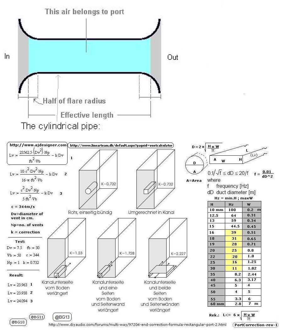
There is no port -at least not in the diagram you show. Just an untapered line, albeit with some variations in cross section around the bends (not necessarily a bad thing). Line length is taken from the throat (sealed end) to the terminus, with an addition for end correction, its acoustic length being a function of both the physical axial length and as relevant its taper.
Thanks for the info, Scott. Yeah, I know it's not a "port," but I wondered whether people would as me what I meant by "line." haha If you don't mind my asking you for more, can I ask you what you mean by 'addition for end correction'? That's something I've heard of but never quite understood. Thanks again!There is no port -at least not in the diagram you show. Just an untapered line, albeit with some variations in cross section around the bends (not necessarily a bad thing). Line length is taken from the throat (sealed end) to the terminus, with an addition for end correction, its acoustic length being a function of both the physical axial length and as relevant its taper.
Cool... thanks for your input, Davor!At point "c" in which case you have an offset driver placement.
Acoustically speaking, a pipe of given length resonates at a slightly lower frequency than is given by a bald axial length & taper ratio due to the exit boundary condition. For untapered pipes of square or circular cross section, a decent approximation is to take tuning frequency as being the pipe length, plus ~0.613 * internal radius added to that length. The ratio tends to vary as the aspect ratio of the pipe increases due to friction.Thanks for the info, Scott. Yeah, I know it's not a "port," but I wondered whether people would as me what I meant by "line." haha If you don't mind my asking you for more, can I ask you what you mean by 'addition for end correction'? That's something I've heard of but never quite understood. Thanks again!
So helpful, Scott... thank you. It seems like the more I learn, the more I realize just how much I DON'T know! I'll add this to my 'data bank.' Thanks again!
......and can be considerably more once any local boundary loading is accounted for. 😉The ratio tends to vary as the aspect ratio of the pipe increases due to friction.

Ok... now you guys are just showing off! HA! I have NO idea what you're talking about, GM, but I'll file it away. Who knows, maybe if I keep at it I'll get it in 5-10 years. 😉
Not really. Seriously?! The info in the link is unfathomable?Ok... now you guys are just showing off! HA! I have NO idea what you're talking about, GM, but I'll file it away. Who knows, maybe if I keep at it I'll get it in 5-10 years. 😉
Hey, Dave... good question. I did the calculations based on Mark's presentation of t-lines on his YouTube channel, Car Audio Fabrication. He broke it down so clearly that I feel good about the math, but it's not entirely clear from his presentation where the line should 'terminate' at the subwoofer [although it looks like he would say (a) or (b); we had a discussion about it on this thread on another forum].Do note that no one has asked if you are modeling this design or just guessing?
dave
Mark?
Hand calculations will only get you a guesed TL (suspected success rate bout 10% if we are shooting for optimum). It is more complicated than the basic math portrays.
dave
Hand calculations will only get you a guesed TL (suspected success rate bout 10% if we are shooting for optimum). It is more complicated than the basic math portrays.
dave
Yeah... don't know his last name. Here is his video (to your point, I think it is a 't-line basics' tutorial):
Something here reminds me of the eternal quote from Top Gear: 'Some say that he only knows two facts about ducks, and both of them are wrong'. 😉
And then he goes on and says that this will not get you there. Indeed that is as far as he gets. Just enuff info to almost ensure a non-optimum line.… sheer basics...
You should forget almost everything he says. Sd for instance had nothing to do with TL design.
It should be noted that in a car, the cabin gain is such that sealed roll-off becomes flat, so unless you ar eainng for too much bass the line will need to be stuffed to aperiodic and will have response similar to the sealed box (that is likely much smaller).
Time to dig into the forum and get a better handle on TL design. It is a WAY deeper subjectthan Mark portrays.
dave
Yeah, I know it's a complicated endeavor, but I thought this might get me started. Figured it would be worth a try... but I'm not so sure now.
Liklehood of anything near optimum is less than 10%.
This has historical info, classic design, and shows some designs that predate proper modeling and some that do not. https://www.t-linespeakers.org/
Do read the: Read me first bit. Do not that the site goes much deeper than what you see on the front page.
The Read me first will take you to Martin King’s site (eventually), the man behind the first really successful TL modeler (sw MIA now unfortunately): http://www.quarter-wave.com/. This site covers a whole lot of modern TL theory and practise.
dave
- Home
- Design & Build
- Construction Tips
- Transmission Line (T-Line): Where to start measuring port length?