If you're not familiar with the coding term "poorly formed", then I guess you wouldn't get the joke.Martin King, using ANSYS, showed that this is not the case. A BR assumes a box not too far from a cube, if you start changing the aspect ratio so that one dimension becomes larger then the others the BR transitions to a mass-loaded transmission line with quite different behaviour.
Tch, tch. You should know better than to make such an assumption. Since I build TLs without stuffing, I have a very clear idea of what's going on.From your comments it is clear you do nothave a solid understanding of a modern TL.
But since I have never seen the point of adding a duct to the end of a TL, why don't you show me one where there's some gain over a BR?
why don't you show me one where there's some gain over a BR?
The official term is restricted terminus and there are many historical antecedants even thou they weren't as well understood.
The advantage is better, lower bass with less sensitivity to dynamic changes in T/S parameters.
If you look at many "tower" BR boxes they are not in fact BR, they are ML-TLs.
dave
True. It's how you get the vaunted "clarity of midrange" the early TLs were known for - by firing the backwave of the driver down a damped pipe. Placing the driver on the side, part way down the pipe, produces the same reflections back at the cone you get with any enclosure.pkitt, placing the driver at the beginning of the line/pipe is NOT "an inherent design defect".
Part of the disagreements over the performance of transmission line loading, is due to the fact that over time the whole purpose of transmission line loading as proposed by Bailey, has been misunderstood. His initial papers specifically showed the superiority of transmission line loading in preserving a close to optimal impulse response. He did this by using an exploding wire technique to produce an internal impulse, which is preserved in transit along a properly damped transmission line. The usual reverberant internal field is largely suppressed. Bailey pointed out the naturalness of the reproduction of bass transients by a TL enclosure. Later proponents started the emphasis on the extended LF cut off, which was not a claim made by Bailey. IMF and TDL were culpable in perpetuating this misconception. The changes to the stuffing from teased long fibre-wool to a sparse weave of fibre-glass and later acoustic foam, are indications of this departure from Bailey’s intent.
Last edited:
The point is that you can get the same impulse response with a combination of electronic filters much more accurately and conveniently, because it is basically a l.t.i. minimum phase system.
The fact that what you are trying to do is to remove all resonances except the lowest one means that the optimum transmission line is a reflex box because in the end you are going to a great deal of trouble to do what a reflex does directly.
In the types of types of TL that Bon describes, you are producing an over large and inefficient sealed box that you can get with an ordinary sealed box and some filters.
rcw
Anyone?Why don't you show me one where there's some gain over a BR?
Can't you just build a few of prototype cabs and see (listen / measure) what you like best? If I were spending that type of money on drivers and crossovers wasting a few dollars on some MDF would be the least of my worries...
I could indeed, a very good suggestion..
But after reviewing the ongoing 'discussion' here, I think it'll be safer for me to go the ported route.
With the issues of room coupling and placement to name a few variables, I'm starting to believe that the (possibly) minor difference between ported and TL is going to be of fairly minor importance in the overall scheme..
From a construction angle, a ported box will make it far easier for me to add as much bracing as I want with a minimum of fuss.
The fact that what you are trying to do is to remove all resonances except the lowest one means that the optimum transmission line is a reflex box because in the end you are going to a great deal of trouble to do what a reflex does directly.
Except that a typical BR box is quite sensitive to dynamic changes in T/S parameters and is actually out of tune more often than it is in.
dave
True. It's how you get the vaunted "clarity of midrange" the early TLs were known for - by firing the backwave of the driver down a damped pipe. Placing the driver on the side, part way down the pipe, produces the same reflections back at the cone you get with any enclosure.
...but will, assuming careful placement, reduce the impact of an undesireable pipe harmonic, usually F3 or F5 being targeted. Higher harmonics are rather more easily addressed with damping.
Note that Bailey didn't exactly do the box type any favours himself by titling his Wireless World articles 'A non-resonant loudspeaker enclosure' and then proceeding, in the text itself, to describe a box that manifestly was resonant, albeit only mildly, and with the harmonic modes well supressed. Olney's acoustic labyrinth papers, frankly, are much better. And pre-date Bailey by three decades.
Last edited:
Tch, tch. You should know better than to make such an assumption. Since I build TLs without stuffing, I have a very clear idea of what's going on.
No doubt. But then, since technically an acoustic transmission line is entirely non-resonant, with the sole object of creating the flattest possible impedance curve (nothing else. That is it. Period.), achieving said without damping is somewhat tricky.
But since I have never seen the point of adding a duct to the end of a TL, why don't you show me one where there's some gain over a BR?
Depends what you are calling a TL. If you mean a QW pipe rather than an aperiodic line (i.e. a 'pure' TL), then it becomes somewhat more obvious. The transitional point between a reflex and what has come to be called a Mass Loaded Transmission Line (MLTL), or Mass Loaded Quarter Wave Resonantor if you prefer, can be said to occur when one dimension has been stretched sufficiently for the resulting eignmode to shift Fb away from what pure Helmholtz math, which is what a BR assumes, says it should be. Usually, the vent needs shortening to maintain the same tuning. A useful point to keep in mind if you're designing a tall, thin vented cabinet, rather than just winging it. Alternatively, you can actively use these as a forced alignment to achieve greater practical LF extension that might (might -it depends on the design) be practical from a straightforward reflex.
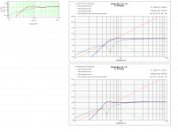
Very quick & dirty comparison attached. Driver is the Fostex FF165wk. Left hand graph from Martin King's MLTL MathCAD sheet of an MLTL -I haven't refined it, because I can't be bothered, but optimising driver location & damping will kill the minor response ripple caused by the pipe harmonics. On the right, FRs from Unibox; upper the usual nominal 4th order flat alignment, the lower assuming the same Vb and Fb as the MLTL.
Attachments
Last edited:
No doubt. But then, since technically an acoustic transmission line is entirely non-resonant, with the sole object of creating the flattest possible impedance curve (nothing else. That is it. Period.), achieving said without damping is somewhat tricky.
That might have been the ideal at one time and many still continue to describe them that way but the truth is that none of these designs are non-resonant transmission lines (as in "the back wave goes down the line never to return").
They are damped resonant pipes designed, hopefully, to have useful bass output from the far end with only moderate upper resonances. There will always be a compromise between those two factors, although a good compromise can be found.
As to flattening impedance, that was never the goal nor is it achieved in any of the designs or simulations that I have seen. Smooth and extended acoustic response is the real goal.
David S
"Defect" was probably inappropriate to use on my part, although I consider locating a driver at the very beginning of the line a poor choice leading to non-optimal (defective) performance unless the intent is true subwoofer use. There are some Fried designs that have this setup and if you model them, their performances are abysmal. Yes, there is a lot of "information" out there on TLs, some of which is misleading, incorrect or mythical. Some of it is quite good, too.
Paul
Paul
pkitt, placing the driver at the beginning of the line/pipe is NOT "an inherent design defect". It is the classic position since Bailey's two papers published in the UK some 4O odd yrs ago (and others see those as revivals of still earlier concepts). There is a mountain of material out there about TLs. I know some drivers are placed in other positions and people build DALINES etc but the diagrams shown here are not "wrong" or merely designed for subs.
If you want to follow it up, the early TLs were called "transmission lines" because of the perceived analogy with electrical TLs. Again, it is true the strict correspondence or one to one relationship has been argued about. In the same way with the Bass Reflex enclosure Thiele's (a great Aussie!) work was generated after he saw the fact that there was a direct parallel between what the BR was doing at resonance and what electrical filter theory predicted.
Cheers, Jonathan
That might have been the ideal at one time and many still continue to describe them that way but the truth is that none of these designs are non-resonant transmission lines (as in "the back wave goes down the line never to return").
I didn't say I was advocating it David, just noting that providing the flattest possible impedance is what an acoustic transmission line is by as strict a definition as we're likely to get. Exaggerating for effect as it were; I don't generally use it that narrowly myself either, 'TL' has become so much of a catch all phrase these days that two pipes that have diametrically opposite design objects can be lumped under the term 😉
They are damped resonant pipes designed, hopefully, to have useful bass output from the far end with only moderate upper resonances. There will always be a compromise between those two factors, although a good compromise can be found.
Agreed. Most of the TLs I've designed fall into this category.
As to flattening impedance, that was never the goal nor is it achieved in any of the designs or simulations that I have seen. Smooth and extended acoustic response is the real goal.
It is in the midrange pipes I've done, largely because it's a damn sight easier and cheaper than achieving the same with electrical filters on a damped out sealed box, which I've never found get the impedance down flat enough to avoid needing some form of compensation if the XO is going to be affected by it. Granted, I'm (very) far from having your levels of expertise in these matters.
Aperiodic lines for flat impedance do sometimes crop up elsewhere, but they've usually been on the DIY fringes, for use with amps that aren't too happy with reactive loads, or with rather questionable drivers. Me, I'd get a better amp / drivers, but to each their own I suppose. 😉
Last edited:
Absolutely not true, at least not in any TLs I've designed and built with the driver offset from the line's beginning. If the line has any reasonable depth behind the driver, the stuffing will absorb almost all of those reflections, and if the line is tapered, the angled divider deflects the tiny amount of reflected signals not absorbed by the stuffing. Again, unless the TL is intended for true subwoofer use only with a typical low crossover frequency, placing the driver at the very beginning of the line will cause ugly and unwanted dips and peaks in the response curve that can't be smoothed adequately by stuffing or other methods without a serious detriment to the bass response.
Paul
Paul
True. It's how you get the vaunted "clarity of midrange" the early TLs were known for - by firing the backwave of the driver down a damped pipe. Placing the driver on the side, part way down the pipe, produces the same reflections back at the cone you get with any enclosure.
Thanks, Scott. I tried, and couldn't get a BR to go down that low without a -2dB shelf. Very interesting....Very quick & dirty comparison attached. Driver is the Fostex FF165wk....
TLS can sound very good. Damping overall requirement and placement is highly dependent on taper and folding gemetry
Note that negative taper lowers the Q and frequency of the fundamental frequency but not of the harmonics so they are no longer odd multiples of the fundamental
The above statement is incorrect regarding the line's fundamental frequency and its harmonics. When a line has a negative taper (area decreasing from driver end to terminus end) the effective length of the line is longer than its actual length, and that makes the 1/4-wavelength resonant frequency lower than a non-tapered line of the same length. The odd multiples of the fundamental follow right along with the change in the fundamental frequency (the 1/4-wave resonant frequency). That's the primary reason for tapering a line, to allow using a line of shorter length. And, the tapering also reduces the magnitude of the natural dips and peaks from those odd harmonics, allowing a lower stuffing density and shorter length of stuffing to achieve a smoother response and less detriment to F3 and lower.
Paul
So , what to do ?
If I'm going to make a box for a sub , how should I formulate the shape of it ?
I read about the Daline ( I didn't know about bailey etc.) and the chamber
for low pass seems reasonable , although it may be incorporated in the very first part of the line , before the first fold .
So the tricky thing is not to make behave like a bass reflex with a very long (tapered ) duct . Still the big volume between the line end and the woofer , when put with an offset, would not be a chamber .
Depends what you're trying to do.
FWIW, Augspurger suggested for a pipe with a coupling chamber that said chamber's Vb should be 1/3 that of the total volume, with the remainder being of the appropriate acoustical length for the target Fp. That's with his alignments, which have a maximum permissable 1dB passband ripple. I don't often bother with chambered types; you can usually get similar or better results without resorting to them. I've done a couple of compact standmount TLs like that though, just because.
FWIW, Augspurger suggested for a pipe with a coupling chamber that said chamber's Vb should be 1/3 that of the total volume, with the remainder being of the appropriate acoustical length for the target Fp. That's with his alignments, which have a maximum permissable 1dB passband ripple. I don't often bother with chambered types; you can usually get similar or better results without resorting to them. I've done a couple of compact standmount TLs like that though, just because.
I don't often bother with chambered types; you can usually get similar or better results without resorting to them. I've done a couple of compact standmount TLs like that though, just because.
And at least 1 big MF.
http://p10hifi.net/tlinespeakers/FAL/box-plans/classicTL-revisited-WD.pdf
dave
- Status
- Not open for further replies.
- Home
- Loudspeakers
- Multi-Way
- Transmission line damping question.