Hello, somebody can help a newbie to find some equivalent/replacement Transistors for my old Technics SA-5200 receiver? I Would appreciate very much your guys help to bring this guy back to life.
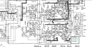
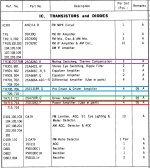
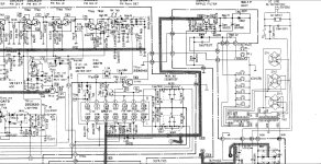
Each transistor is marked in the schematics image, and their role in the circuit is also marked on the parts list image below.
Thank you all !!!
TR 705, 706, 709, 710 -> 2SC1318R , Q
TR 110, 707, 708 -> 2SC828Q , R
TR 711, 712 -> 2SA720R , Q
TR 713, 714, 715, 716 -> 2SD318Q , P
Each transistor is marked in the schematics image, and their role in the circuit is also marked on the parts list image below.
Thank you all !!!
TR 705, 706, 709, 710 -> 2SC1318R , Q
TR 110, 707, 708 -> 2SC828Q , R
TR 711, 712 -> 2SA720R , Q
TR 713, 714, 715, 716 -> 2SD318Q , P
Attachments
If you can't find these parts on Mouser, they are probably long past obsolete.
You can attempt to find substitute transistors but maybe the best outcome occurs when you recycle this old amp because there is some risk of ruining your speakers.
https://alltransistors.com/transistor.php?transistor=11743#google_vignette
I repaired an old NAD C320 a few times. It had obsolete BJT like 2SC669A. Finally, I scrapped the main board and replaced it with 3886 modules.

But there is nothing special about any of those transistors. And the amp runs on very low voltage, as receivers go. The current production power transistor is the KSD880. The KSD526 was the go-to for years, but just recently discontinued. Truth is almost any TO-220 NPN “epitaxial base” type rated 6A, 60V or more will work. The KSD/2SD types are only rated 3A, but their current gain holds up better than a US or EU type, so you need 6A versions of those to get equivalent gain. If you are going to beat on it with 4 ohm loads, use higher rated types - 10 or 15A, like 2N6488.
The drivers are nothing special either. You just need Jap 2SA/2SC (Korea KSA/KSC) type to get the right pin out. US (2N, MPSA) or EU (BC) types rated 60V, .5A, hFE 200 or more would work but you’d have to bend the leads to get B,C and E in the right place. Lower gain parts would probably work, but the higher the better and no problem to get 200 at this low power level. The bias spreader can be pretty much any general purpose type, in the right case, with the right pin out. So it can easily mount to the heat sink. The most important part there is for it to FIT properly for good thermal transfer.
The original driver types (A720 and the NPN) are known problem children. They can just go bad over time. The A720 was quite popular as in input differential amplifier but they get noisy as hell when they go bad.
Not if you fix it first.You can attempt to find substitute transistors but maybe the best outcome occurs when you recycle this old amp because there is some risk of ruining your speakers.
I had 2 amps with 2sc2229/2sa949 (B&W TV output) VAS's. Just Cob,Hfe,fT , Voltage .... our favorite TTC/TTA004 's - perfect sub.
Most of the 2SC/A's are faster types. Like with caps (and the TTA/C"s) , a higher voltage is alright.
The only "bad" subs are wildly different Ft's and gain. Some older circuits don't like the faster (fT) newer devices. They were compensated for slow , high
Cob older devices.
Any 80's and newer can use MJE-NJW driver/ outputs sets. Or MJE - Sanken MT-100's . Sanken makes the best current outputs for cheap OEM 40-60W amps.
Most of the small signal to-92 devices can be ordered ECB or EBC , or you can find multiple subs with either pinout.
OS
Quite hefty 8A devices. I've seen 2 pair per channel match a TO-3P output stage.Mje15030
OS
Back when I bought this receiver, I accidentally turned the receiver on with the voltage switch on 110v position, on a 220 volts outlet, The tech guy that repaired the first time, replaced the four (TR 713,714,715,716) 2SD318Q power amplifier transistors by the MJE3055T, Also replaced two of the 2SC828Q(TR 707,708) by the BC337 transistor, With this new ones, the receiver worked for years, until over a year ago, one of the power amplifiers transistors blowed up.
Long story short, I replaced all four transistors myself and turned the thing on, now just there was audio output for a second and the audio soon disappear. Decided sent the unit to another "Tech", he kept my receiver for a year, and now many of the components are missing(All the transistors mentioned)and a few resistors, and he couldn't fix it. I could notice he replaced two more transistors, the TR 710,712 (2SC1318R, 2SA720R), by a BC337, BC327, my question is, It's Ok I keep all these ones the tech guys replaced, or should I search for better ones among the transistors you guys recommended.
Sorry any english mistakes, and Thank you all for helping me!
Horrible old slow devices 2mHz Ft / gain as low as 20 ! Used for Voltage regulators - not audio !MJE3055T
All the originals appear to be >100 gain /20 - 100Mhz , and actually have a Cob spec.
"Tech" just matched the voltages.
MJE15030 is perfect output - 30mHz/40- 50 gain - 8A !!
They are alright , 200mhz/100-200 gain/low Cob , standard modern small signal fare.BC337,327
Edit - the circuit was designed for fast/med to high gain devices.
Also
- C711/12 is "bootstrap cap" - very important that it is perfect (new). best to put 25-35V NP 33uF.
-C705/6 is DC cap 47uF/ 25V , offset will be better , and C707/8 -180pF is the main HF compensation - optional -put a nice silver mica quality one there.
- and if it has not been recapped ,the two input caps C701/2 .47u ?? I'd put a HQ 1uF 35V there. MIGHT SOUND BETTER THAN NEW !!
OS
Last edited:
For the 2SC1318 my 1998 substitution manual states the following as replacements:
Sanyo 2SC3708
Toshiba 2SC1626
NEC 2SC2002
Hitachi 2SC1213A
Mitsubishi 2SC3581
ROHM 2SC1741AS
For the 2SC828:
Toshiba 2SC1815
NEC 2SC945
Hitachi 2SC458
ROHM 2SC1740S
For the 2SA720:
Toshiba 2SA817
NEC 2SA953
Mitsubishi 2SA1399
ROHM 2SA854S
For the 2SD318:
Toshiba 2SD526
Hitachi 2SD1135
Matsushita 2SD1266
ROHM 2SD2576
Happy hunting!
MJE3055T: All wrong. Might work, but the gain is stupid low on most “3055” types, even down at 1 amp. You would be better off with TIP41. Originals are only 3 MHz types, no need for anything fancy - just not total junk. MJE15030 or D44H8 would work, but unnecessary here.
The BC237/337 are a little under-rated for voltage. They probably work fine, but if you get one that can’t block the full 43V, it will go bang. Most will, but it’s not guaranteed by spec. The pin out is different from the Jap types too but if you know what you’re doing it’s not a problem. I used to use the old “giant TO-92’s” in places like this to get a bit more ruggedness, but sources of those have dried up.
The BC237/337 are a little under-rated for voltage. They probably work fine, but if you get one that can’t block the full 43V, it will go bang. Most will, but it’s not guaranteed by spec. The pin out is different from the Jap types too but if you know what you’re doing it’s not a problem. I used to use the old “giant TO-92’s” in places like this to get a bit more ruggedness, but sources of those have dried up.
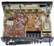
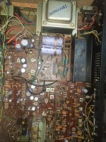
Usually when a vbe multiplier transistor AND A thermistor are used, the transistor goes on the heat sink and the thermistor does not.It also looks like TH701 and 702 are thermistors that control the bias devices tr707/8. They are small- black?
2 lead resistors that need to be on the heatsink with a little white compound.
Cute little amp !
Interesting the use of a double boot strap. In the usual collector load of the VAS, and for the whole negative rail of the front end too. To make the absolute most of the 43V power supply. That’s the biggest reason that just replacing the whole thing with LM3886’s isn’t the best idea. The front end on those is horribly inefficient - and you might get to within 5 or 6 volts of either rail. It just can’t be spared here. It makes a nice, easy low distortion solution, but always less power than a discrete design on the same power supply.
They are not on the heatsink, only the 4 power amplifiers, and the TR707,708 are. Those thermistors I think it's the ones I marked on this picture I took.It also looks like TH701 and 702 are thermistors that control the bias devices tr707/8. They are small- black?
2 lead resistors that need to be on the heatsink with a little white compound.
Cute little amp !
Attachments
Normally, those TO-92’s are mounted to the heat sink. It’s possible that as low power as this is, it’s good enough with them near the heat sink - it just won’t generate a ton of heat to compensate for. About 6 watts per power transistor worst case average, with real world about half that. It will warm up, but not burn your hand hot.
I see that BC and E are labeled on the board. Good news if you’re subbing parts because there are actually FOUR possible pin arrangements for those little TO-92’s. ECB (normal for jap), BCE (some early Jap types, if they have the ring around the bottom), EBC (JEDEC), and CBE (EU types). TO-220’s are at least consistent -they ALL go BCE.
I see that BC and E are labeled on the board. Good news if you’re subbing parts because there are actually FOUR possible pin arrangements for those little TO-92’s. ECB (normal for jap), BCE (some early Jap types, if they have the ring around the bottom), EBC (JEDEC), and CBE (EU types). TO-220’s are at least consistent -they ALL go BCE.
Sorry the delay guys, my old analog Kyoritsu meter went bad, I ordered a aneng8008 from china so I can keep looking for bad transistors 😛, I think I will use the TIP41 for the power amp, since I can find this one easier in my country than the Mje15030, not sure about the drivers, and the (muting switching, thermo compensation)TR707,708 yet
Thanks, I will make sure to replace those as well !!!, anything else could be bad besides the transistors?- C711/12 is "bootstrap cap" - very important that it is perfect (new). best to put 25-35V NP 33uF.
-C705/6 is DC cap 47uF/ 25V , offset will be better , and C707/8 -180pF is the main HF compensation - optional -put a nice silver mica quality one there.
- and if it has not been recapped ,the two input caps C701/2 .47u ?? I'd put a HQ 1uF 35V there. MIGHT SOUND BETTER THAN NEW !!
OS
The last technician removed many of the resistors around the drivers R731,733,734 and 730, the R743 he replaced was all burned.
The only reason I mentioned the input caps (C701/2) is that they seem quite small and might cut in to your LF response.
The feedback is relatively high impedance on this amp (56K) , so that is why they chose such a small value.
Most forum DIY amps like this with a lower imp. use a 4.7uF (27K). So yours should be 2.2uF to get no rolloff around 20hz.
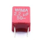
A wima poly 2.2uF @ 50V non-polar is the ideal input cap (what I would put in).
PS - my Sonance 260 recapped amp had a 1uF , I put a pair of those below in - very good sound.
OS
The feedback is relatively high impedance on this amp (56K) , so that is why they chose such a small value.
Most forum DIY amps like this with a lower imp. use a 4.7uF (27K). So yours should be 2.2uF to get no rolloff around 20hz.
A wima poly 2.2uF @ 50V non-polar is the ideal input cap (what I would put in).
PS - my Sonance 260 recapped amp had a 1uF , I put a pair of those below in - very good sound.
OS
Attachments
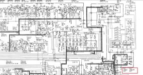
Well guys I finally had the time and replaced everything, the thing now is, I powered the thing on with a 100W bulb in series, and the bulb lit up at full brightness, no signs of life in the receiver, I could feel a burnt smell being released on the bridge rectifier, one of the dual diodes is bad(D801) with one of the legs loose and reading random values on the DMM , the other(D802)looks fine measuring (0.589~0.590V) on both directions, what could caused this guy to go bad? Should I replace both of them?
Also I couldn't find any datasheet about it, what could be a replacement for them?
The Diodes are marked with a red box on the schematics below.
I'm suspecting the "Tech" did something bad on purpose to ruin the receiver once I was a little bit salty with him, because he kept the receiver for over a year and returned the thing missing many of the components.
The only issue in the first place was the audio 😢.
Appreciate once again your guys time, patience and help 👍
Attachments
The original failure (likely shorted output transistors) probably took out the bridge rectifier from too much current draw. I’d replace both of those obsolete dual diodes with a single 4-legged bridge rectifier. It only needs to be 4 or 6 amps, but a 10 amp may not be any physically larger. 100 volts is enough, 200 is common, 600 is overkill but won’t hurt anything. Four 3 amp single diodes (ie 1N540x) but they tend to have leads that are too fat to fit in many PCBs. They use the leads to conduct the heat out. Bridge rectifiers (the 4 legged variety) usually have a mounting hole to put a heat sink on if you pull enough current to warm it up. 1 amp (or 1.5 amp) diodes may be enough but I wouldn’t if I was designing it. The DC current draw will hit about 2 amps at full volume and I’d prefer to have some margin.
Not sure a 4 legged would fit there, there's 2 dual capacitors between them, 4 of the IN4007's wouldn't work here? I have a few around, also have the IN5404, but as you said they're too fat to fit.
I noticed the R750 isn't the same as the schematics(2.2ohms 1/8), It was replaced by a 4.7ohm 1/4 can I keep this one?
I noticed the R750 isn't the same as the schematics(2.2ohms 1/8), It was replaced by a 4.7ohm 1/4 can I keep this one?
- Home
- Amplifiers
- Solid State
- Transistors replacement for my Technics SA-5200 receiver