Hi everybody,
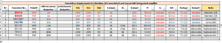
I recently acquired a pair of Meridian 105 monoblocks and a Sansui A40 integrated Amp that are blown. My problem is getting hold of the obsoleted transistors. I have substituted the Meridian BD419/420 pair with the BD139/140 pair. For the Sansui A40 pair of 2sc1827/2sa769, I have used TIP41c/42c pair. Please see attached table. They seems to be working but I wish to if these substitutes will have problems in the long run. Which pairs are best for the meridians? Thanks in advance.
Edit:Only one of the meridians was blown.
Attachments
Last edited:
Bias value for meridians
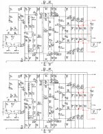
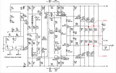
Also, does anyone know the bias voltage for the meridians? Right now I have set one of the mono at around 9mV and 14mV. The other was 10mV. Please see attached schematic. Any help is greatly appreciated.
Also, does anyone know the bias voltage for the meridians? Right now I have set one of the mono at around 9mV and 14mV. The other was 10mV. Please see attached schematic. Any help is greatly appreciated.
Attachments
Meridian has not published those specs, not even in the service manual. I've had a couple pairs of 105s and can say that at ambient room temp...72deg., in open air (on a table), at idle fully warmed up, the heat sinks verge on being uncomfortable to keep the backs of your fingers in contact. So quite warm, but not quite hot.Also, does anyone know the bias voltage for the meridians? Right now I have set one of the mono at around 9mV and 14mV. The other was 10mV. Please see attached schematic. Any help is greatly appreciated.
Hope that helps.
Thanks Discopete. Does that mean that the values aren't important? Right now my meridians are just running warm.
With amplifier that work at +/-55V i wouldn't use the BD139/140 because C-E is 80V.
also i think you need calibrate bias voltage for 5mv each Power Transistor (10mv NPN E TO PNP E)
also i think you need calibrate bias voltage for 5mv each Power Transistor (10mv NPN E TO PNP E)
Last edited:
motronix is probably close to the mark. However I would not consider my observation without merit. 5-7 mv at the emitters will most likely result in that heat range. Just calibrate both amps the same.Thanks Discopete. Does that mean that the values aren't important? Right now my meridians are just running warm.
Thanks again guys. The TIP 41/42c is at 100v C-E but the hFE is at lower range. I do not know how important this is to the Amp but at 100v, it is the same as the original transistors. So, 5mV should be OK for the bias of this Amp. It seems to be running just slightly warm.
Thanks.
Thanks.
for the driver TTC004B + TTA004B will do the best job. you can see at mouser.
amplifiers with MJ15003/4 transistors mostly calibrate with higher bias like 17-20mv each transistor.
amplifiers with MJ15003/4 transistors mostly calibrate with higher bias like 17-20mv each transistor.
It looks like a triple EF (Locanthi triple) with a 2pair output stage.
The optimal ClassAB bias is likely to be around 20mVre (or 40mV across the series pair).
This will pass ~91mA through all of the output devices.
The heatsink dissipation will be around 20W, plus some from the drivers.
I would not use BD139/140 in an amplifier with +-55Vdc supplies, not even in +-50Vdc supplies
Thanks Andrew. The heatsink of the meridians are mounted at the bottom. I'm afraid if it gets too hot. I'll try to get the ttc004b pair.
I would suggest MJE15034/MJE15035 drivers. The TTC004B gain is rated at only 100mA, which may be OK but having more current drive available may be preferable. I take it that this amplifier is something like 100W/8 ohms; maybe spec'd a little higher. At 5A output (and currents might be pulsed higher than this) the MJ15003/4 gain is 25, so needs 200mA. I would by choice probably use the TTC004B or similar as the first stage of the triples rather than a TO-92 device, but the designers probably wanted to keep costs low.
Dear john_ellis
this is "small" amplifier (it's not 300W or more) that work with +/-75V. for this amplifier Toshiba TTC Transistors it's perfect. the GR8 MJE transistors is for use in much more higher C-E voltage and current it drive lots of final stage transistors. and the price? TTC $0.49 MJE $1.31
this is "small" amplifier (it's not 300W or more) that work with +/-75V. for this amplifier Toshiba TTC Transistors it's perfect. the GR8 MJE transistors is for use in much more higher C-E voltage and current it drive lots of final stage transistors. and the price? TTC $0.49 MJE $1.31
The mj15003/4 are each 250W devices. Giving a total device power of 1000W
Expect these four devices to give a reliable maximum output power of 200W
With a +-55Vdc supply expect the amplifier to have a maximum output of 120W to 150W into 8r0 depending on the mains voltage fed to the primary.
If one were to reduce the load to 6r0 resistive, the maximum power will be 180W to 200W.
If you can keep the amplifier cool enough, the output stage will be reliable driving 8ohms all day long.
Alternatives transistors and meridian 101b pre Amp connection
I'm unable to get the TTC004b locally. I'm looking at the 2sc4370 and hopefully I can find it's complementary pair as well. They have almost the same specs as the TTC004b. Please see attached table.
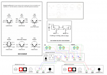
Also, I'm not sure if I got the meridians pre-amp DIN connections right. The DIN diagram connection are from the meridians manual. I have drawn them up but am confused about the connection between the pre amp (101b) and the monoblocks (105). Please see diagram. Is my drawing of the pre Amp connection between the Amp and the sources correct?
Thank you.
I'm unable to get the TTC004b locally. I'm looking at the 2sc4370 and hopefully I can find it's complementary pair as well. They have almost the same specs as the TTC004b. Please see attached table.
Also, I'm not sure if I got the meridians pre-amp DIN connections right. The DIN diagram connection are from the meridians manual. I have drawn them up but am confused about the connection between the pre amp (101b) and the monoblocks (105). Please see diagram. Is my drawing of the pre Amp connection between the Amp and the sources correct?
Thank you.
Attachments

KTB631K+KTD600K
you can find at this ebay store the perfect complementary pair KTB631K+KTD600K.
this store have Only original items
5X KTB631K+ 5X KTD600K EPITAXIAL PLANAR PNP+NPN TRANSISTOR Original KEC TO-126 | eBay
you can find at this ebay store the perfect complementary pair KTB631K+KTD600K.
this store have Only original items
5X KTB631K+ 5X KTD600K EPITAXIAL PLANAR PNP+NPN TRANSISTOR Original KEC TO-126 | eBay
- Status
- Not open for further replies.
- Home
- Amplifiers
- Solid State
- Transistors for Meridian 105 and Sansui A40