Hi,
I have an active filter circuit in a bipolar power supply to filter out the ripple voltage. The filter circuit by itself is quite simple and uses a pair of transistors in a darlington configuration.
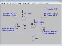
I have put the circuit together and have verified that it works. The ripple before it is around 1 vpp and after it about 2 mvpp. The supply is under a load of 379mA, which is about half its max load. So the MJE collectors, see below, have 379mA collector current going through them.
I measured the base-emiiter voltage of the transistors, here's what i got:
-MJE2955T, 0.698v
-BD239C, 0.581v
-MJE3055T, 0.698v
-BD240C, 0.580v
I'm a little worried that they're not fully on, since the voltages seem a bit low for bipolar types, which i thought were around 0.7v. Also, in the respective data sheets, i didn't find anything except for some max Vbe values. For the MJE's its 1.8/-1.8 and for the BD's its 1.3/-1.3.
Should i worry about these values?
Cheers,
Chris
I have an active filter circuit in a bipolar power supply to filter out the ripple voltage. The filter circuit by itself is quite simple and uses a pair of transistors in a darlington configuration.
I have put the circuit together and have verified that it works. The ripple before it is around 1 vpp and after it about 2 mvpp. The supply is under a load of 379mA, which is about half its max load. So the MJE collectors, see below, have 379mA collector current going through them.
I measured the base-emiiter voltage of the transistors, here's what i got:
-MJE2955T, 0.698v
-BD239C, 0.581v
-MJE3055T, 0.698v
-BD240C, 0.580v
I'm a little worried that they're not fully on, since the voltages seem a bit low for bipolar types, which i thought were around 0.7v. Also, in the respective data sheets, i didn't find anything except for some max Vbe values. For the MJE's its 1.8/-1.8 and for the BD's its 1.3/-1.3.
Should i worry about these values?
Cheers,
Chris
Attachments
If the transistors were turned completely "On" there would be no regulation and therefore no ripple rejection.
The voltages, to me, seem about right.
If you increase the load, the voltages will increase accordingly, but only marginally. Reducing the load will have the opposite effect of course.

The voltages, to me, seem about right.
If you increase the load, the voltages will increase accordingly, but only marginally. Reducing the load will have the opposite effect of course.
Nothing magic happens at 0.7V. BJTs follow an exponential law. Newbies may be taught that BJTs 'turn on' at 0.7V. Not true, but a useful simplification until they learn about how BJTs really work. Typically, the bigger the transistor the smaller the Vbe for a given collector current.
One more....
Thanx for the quick replies!
Just one more comment from my side. The data sheet of my BD239 has a
graph of Base-Emitter Voltage vrs. Collector Current.
BD239 datasheet pdf datenblatt - Power Innovations Ltd - NPN SILICON POWER TRANSISTORS ::: ALLDATASHEET :::
The curve on the graph begins at a collector current of 30mA and ends at 1000mA. At 30mA, the BE voltage here, is a little above 0.6 volts. At 1000mA its about 0.84 volts. To the left of 30mA there's no data or graph!?
In my circuit at the give MJE2955 collector current of 379 mA, the gain is around a 100. So its req. base current would be around 3.6 mA. This is approx. the collector current of the BD239.
In my circuit I measured 0.620v, can I assume the graph is flat there if anything at all?
Sorry for being so paranoid but I am a little of a newbie here and still quite unsure of my self.
Thanx,
Chris
It's not flat, but close enough that most of the time the assumption is a valid one. In your circuit you'll be fine assuming 0.65V, or so, and realizing that nothing is wrong if a measurement is between 0.5V and 1V.In my circuit I measured 0.620v, can I assume the graph is flat there if anything at all?
IIRC, the Vbe changes 26mV for every change in Ic by a factor of 10.
The graphs are all 'typical values' and may vary rather widely.
jan
The graphs are all 'typical values' and may vary rather widely.
jan
More importantly they are measured under pulse conditions. In the real world some devices get hot and the threshold falls ~2mV/CThe graphs are all 'typical values' and may vary rather widely.
jan
- Status
- Not open for further replies.
- Home
- Design & Build
- Parts
- Transistor Threshold Voltage