A digital dweeb is requesting the assistance of any knowlegable analog guru out there.
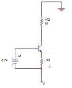
Consider the simple NPN current source shown in the attachment.
If V1 is an ideal 0 impedance voltage source (referenced to -V) we know that the voltage across R1 is about 5v. Using ohms law we can determine the current through R2 is 5v/0.1 = 50A. (I know these numbers are large, I just picked them for ease of calculation).
Here is my question. Since the current through r2 is largely independant of beta, could we conculde that this transistor circuit is very resisant to thermal runaway (or anything else that would cause beta to increase)?
Thanks in advance for the help.
Attachments
Hi,
Unfortunately, your values are completely unrealistic - you'll need more than 800 V supply just to get this circuit into a linear region 🙂 - and dissipation on R2 would be about 40,000 W . It is, I suppose, possible - but I wouldn't try it at home... .
For a bit more down-to-earth approach, let's take R1 = 5 Ohm. Than the current would be about 1 A and supply voltage over 24 V will work. And yes, this circuit will only slightly increase the collector current with the temperature rise - main influence is the Vbe voltage ("0.7 v") - it has a negative TC about -2mV/degree C. So 100 degrees increase in temperature will result in 200 mV increase in voltage on R1 and the collector current - about 4% .
Al
hugeli60 said:Using ohms law we can determine the current through R2 is 5v/0.1 = 50A. (I know these numbers are large, I just picked them for ease of calculation).
Unfortunately, your values are completely unrealistic - you'll need more than 800 V supply just to get this circuit into a linear region 🙂 - and dissipation on R2 would be about 40,000 W . It is, I suppose, possible - but I wouldn't try it at home... .
For a bit more down-to-earth approach, let's take R1 = 5 Ohm. Than the current would be about 1 A and supply voltage over 24 V will work. And yes, this circuit will only slightly increase the collector current with the temperature rise - main influence is the Vbe voltage ("0.7 v") - it has a negative TC about -2mV/degree C. So 100 degrees increase in temperature will result in 200 mV increase in voltage on R1 and the collector current - about 4% .
Al
- Status
- Not open for further replies.
