Hi Harry,
Okay, first pick up whatever you need in the way of thermal compound and insulators. Once everything is back together properly we shall bias the unit. Meantime I'll look for that information.
Anyone else is free to jump in here if you have the bias info on this unit.
-Chris
Right on! Cool!At 1:20. this morning I fired it up successfully I stayed very reserved with the volume control.
Okay, first pick up whatever you need in the way of thermal compound and insulators. Once everything is back together properly we shall bias the unit. Meantime I'll look for that information.
Anyone else is free to jump in here if you have the bias info on this unit.
-Chris
Hi,
EF output stage or CFP outputs?
Do we stay with Carver's set up procedure or, if different, set up the EF with Vre between 15mV and 25mV under all operating conditions.
EF output stage or CFP outputs?
Do we stay with Carver's set up procedure or, if different, set up the EF with Vre between 15mV and 25mV under all operating conditions.
Hi Andrew,
EF, but not completely normal.
Try setting the bias anywhere between 10 and 20 mA . There is only one pair of outputs, the rest are commutators. I don't have this manual any more.
Carver does not normally run things too hot.
-Chris
EF, but not completely normal.
Try setting the bias anywhere between 10 and 20 mA . There is only one pair of outputs, the rest are commutators. I don't have this manual any more.
Carver does not normally run things too hot.
-Chris
Chris, Just a little clarification when I said I fired it up I meant I fired it up with the outputs installed. Also I found a little more info myself with regard to the bias process. Had the unit playing today at about 20 or 30 watts per channel into a four ohm load to boot for about 20 minutes. Removed the input source and checked the test points which are the .22 ohm 5 watt emitter resistors, specs call for 6 millivolts +/- 1 millivolt. I am reading 2 millivolts on both channels and the pot seems to have no effect on the voltage at least on the one channel as I did not try to adjust the other one. For the heck of it I measured the DC offset voltage at the speaker out terminals 2.5 MV and 6.5 MV . The unit playing for 20 minutes showed no audible signs of distortion and seemed to run cool. I believe the drivers were warmer than the outputs. I thought about heat sinks on those what do you think?
Thanks, Harry
Thanks, Harry
Hi,
any ideas why Carver's bias current is set so low?
6mV is a lot less than the 15 to 25mV range.
Surely it's not just a temperature thing?
any ideas why Carver's bias current is set so low?
6mV is a lot less than the 15 to 25mV range.
Surely it's not just a temperature thing?
Hi Harry,
Okay, so I can see the amp is working.
These have two circuits for bias. One is right at the drivers I think, fixed. It may go short or leaky. the bias circuit further back is the adjustable one. Man, I wish I had the manual. This memory stuff is shaky.
Some of the earlier ones ran hotter, check the bias circuits carefully. There may be some signal diodes in there that can short or leak causing you some trouble.
Hi Andrew,
Often, if you adjust the bias current while watching the distortion residuals you will see a point where the crossover glitches disappear. Often there is no improvement past this point is THD numbers or the residual stuff you can look at. When you measure this value, you may find it much lower than you expected.
I like to use about 10 KHz at a low level into a 4R load. You can try this out at different levels and loads. You will find th at higher signal levels will mask the crossover notch you are trying to look at.
-Chris
Chris,
At this point I cleaned the 2 adjustment pots and began to question the Rat Shack meter I was using. Now using my Fluke DMM the lowest readings I can achieve 7mV and 8mV . After that I attempted to remove the solid state relay that I previously spoke of and the protection relay will not energize. What may be the cause for this ? So for now I put the relay back in the circuit and the unit is again operational. Thanks, Harry
At this point I cleaned the 2 adjustment pots and began to question the Rat Shack meter I was using. Now using my Fluke DMM the lowest readings I can achieve 7mV and 8mV . After that I attempted to remove the solid state relay that I previously spoke of and the protection relay will not energize. What may be the cause for this ? So for now I put the relay back in the circuit and the unit is again operational. Thanks, Harry
Hi Harry,
Okay .... very, very carefully, re-install the triac. Ever so slowly and carefully, replace the top and bottom covers. Back out of the room and ask a good technician in your area for help.
If there is no one in your area that is specifically trained in these Carver amps, find one and ship the unit to him or her.
You are now messing around in the primary energy regulation circuit. If you were to have shorted this part out the amplifier (and you) may have been badly damaged. I'm not kidding!
-Chris
Holy Oh-Oh Batman!!!. After that I attempted to remove the solid state relay that I previously spoke of and the protection relay will not energize.
Okay .... very, very carefully, re-install the triac. Ever so slowly and carefully, replace the top and bottom covers. Back out of the room and ask a good technician in your area for help.
If there is no one in your area that is specifically trained in these Carver amps, find one and ship the unit to him or her.
You are now messing around in the primary energy regulation circuit. If you were to have shorted this part out the amplifier (and you) may have been badly damaged. I'm not kidding!
-Chris
Harry,
Give me another call tonight. I had an "emergency" at work and had to run out at 7:00pm. Make sure R506 is (56K res) and install (50K pot) in SVR503 volt adj, power supply voltage MUST NOT be higher then 74V on the top tier. If power supply is adjusted too high the caps can explode. Bias voltage should be 6mv, are the TH101 & TH102 thermistors still installed next to the heat sinks?
Chris,
After talking to Harry it seems someone installed a solid state relay to bypass the speaker relay?? He said the power supply is working properly, but there is no volt adj pot? he said it just has a jumper installed where the pot should be, sounds like very dangerous tech worked on this amp before.
Hi toddyaudio,
Yes, Harry sent me a PM to explain the exact situation (hard to imagine without pictures).
-Chris
Yes, Harry sent me a PM to explain the exact situation (hard to imagine without pictures).
I didn't know about that! This is very dangerous indeed. I'm glad you are close enough to help here. Another example of the damage that a technician "who knows better" than the design team eh? These guys are the ones that keep me up at night.He said the power supply is working properly, but there is no volt adj pot? he said it just has a jumper installed where the pot should be, sounds like very dangerous tech worked on this amp before.
-Chris
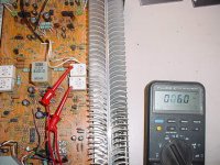
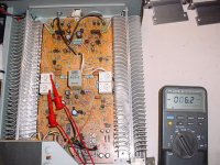
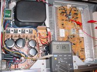
Carver M500 bias
2 photos show bias L / R measurement points (6mv). Other photo shows HV measurement point (74v), plastic trimmer is resting on SVR503 (HV adj pot). All the elec caps were replaced within the last year, they are all still available in the same case size (or smaller).
2 photos show bias L / R measurement points (6mv). Other photo shows HV measurement point (74v), plastic trimmer is resting on SVR503 (HV adj pot). All the elec caps were replaced within the last year, they are all still available in the same case size (or smaller).
Attachments
Hi toddyaudio,
Your elastomers need cleaning in your (very good) meter. That should make the display like new. Use 99% isopropyl alcohol on a Q-tip to clean the ends and the PCB traces.
If I recall correctly, there was a modification to reduce the temperature of those TO-92M transistors near the back. Resistor values were changed. 2SC2705 and 2SA1145? Just off the top of my head.
Those pictures bring back memories for sure.
-Chris
Your elastomers need cleaning in your (very good) meter. That should make the display like new. Use 99% isopropyl alcohol on a Q-tip to clean the ends and the PCB traces.
If I recall correctly, there was a modification to reduce the temperature of those TO-92M transistors near the back. Resistor values were changed. 2SC2705 and 2SA1145? Just off the top of my head.
Those pictures bring back memories for sure.
You can attach one per post, or host the image elsewhere and provide many links per post.Can't figure out how to send more then 1 photo file per reply, this is the other bias channel measurement point.
-Chris
Todd,
As per your post, Thermistors are present on the heatsinks and I measured the B+ at 80.1 volts. Installed the 50K pot and checked R 506 which measured 47K so I replaced it .Now B+ is 76.9 volts and will not adjust any lower. Question, Would the 80.1 volts activate the protection circuit and not allow the relay for the speakers to engage?
Chris,
I tried to send you the service manual but it would not upload on my end. Will try to work out something on my end. Harry
Hi Harry,
Thank you. I'd like to regain my manual collection! 😉
The high voltage would not prevent the relays from closing. Find the emitter resistors and measure from there to ground for each channel. A high voltage there (DC offset) would do this. Sounds like you need that service done that I mentioned earlier.
-Chris
Chris, Measured the 4 emitter resistors to ground per your suggestion. Values are as follows 4mV, 6mV, 10mV, 11mV. Bias is at 4 mV I had it set at 6mV. I assume that the 3.2 volt drop in B+ is what droppped the bias to 4mV. I dont think this would cause the protection circuit to activate. Anything else I should be looking for? Thanks,Harry
Hi Harry,
Your offsets are okay indeed.
Most Carver protection will trip on any one of the following:
1. DC offset in either channel
2. Imbalance in the supply voltages, not the wrong voltages.
3. Excessive current (Not sure - I would need the manual to confirm).
These did have a weakness with the solder joints near the rear of the chassis. Excessive heat. Most of the overheating issues will cause a DC offset. You would have seen that.
So flip it over an look at those solder joints. Use liquid solder flux (for electronics!) and resolder them. You may need to remove the old solder - add fresh first as it makes things easier. Then resolder. Clean off the flux so you can see the board clearly. Look for solder whiskers and shorts.
-Chris
I checked the solder joints and found a few that were sloppy not what I would call cold anyway I redid those and no change. I received the proper schematic today and the quality of this one is far worse than the one I sent you yesterday. I will attempt to darken it up some on the copier as well as enlarge it slightly. This one is for the Carver M500 which is the amp I actually have. Harry
- Status
- Not open for further replies.
- Home
- Amplifiers
- Solid State
- Transistor Substitution