Hello all,
FIRST CONCERN :
I am wondering myself about the impact of the transistors themselves on the amplifier characteristics. The question came to me because a transistor of my amplifier has gone faulty (a 2SB1184, in my Primare a30.1). Looking for a replacement, I've wanted to understand how much of a change would it have if I replace it with a quite close transistor.
The question would get down to :
" Is it the circuit around the transistor that is responsible for the global characteristics of the amp (frequency response, THD, ...); or is it the really particular behavior of the transistor under the working conditions that will produce most of the characteristics of the amp ? (obviously, given that the transistor can according to its datasheet follow the lead of the circuit) "
Put in an other way :
" is changing a transistor for an other, equivalent in spec, likely to change the characteristics of the amp, and so its sound ? "
SECOND CONCERN :
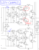
With my example ! : The amplifier is really fully balanced. So there is in fact four amplifiers inside, two for each polarity per channel. It's likely that I will have to find a replacement for my 2SB1184 (see schematics). In this case, I have some questions :
Thanks all !
FIRST CONCERN :
I am wondering myself about the impact of the transistors themselves on the amplifier characteristics. The question came to me because a transistor of my amplifier has gone faulty (a 2SB1184, in my Primare a30.1). Looking for a replacement, I've wanted to understand how much of a change would it have if I replace it with a quite close transistor.
The question would get down to :
" Is it the circuit around the transistor that is responsible for the global characteristics of the amp (frequency response, THD, ...); or is it the really particular behavior of the transistor under the working conditions that will produce most of the characteristics of the amp ? (obviously, given that the transistor can according to its datasheet follow the lead of the circuit) "
Put in an other way :
" is changing a transistor for an other, equivalent in spec, likely to change the characteristics of the amp, and so its sound ? "
SECOND CONCERN :
With my example ! : The amplifier is really fully balanced. So there is in fact four amplifiers inside, two for each polarity per channel. It's likely that I will have to find a replacement for my 2SB1184 (see schematics). In this case, I have some questions :
- I should find a transistor with a complementary one and change the complementary as well, right ?
- I should change all four of push-pull pairs (the two in the right channel and the two in the left), right ?
Thanks all !
Attachments
Welcome to diyAudio 🙂
Although its quite a complex situation it can be simplified...
If you pick a suitable transistor the characteristics of the amp will remain the same, the gain, the frequency reponse and so on is determined by the external components. Pick an unsuitable device and you might (unlikely for this one) have stability issues (high frequency oscillation) and get the main characteristics totally wrong (voltage/current/power dissipation) and the device would fail.
Those are driver transistors and ideally should be a complementary pair. Its notable the output transistors seem to have no emitter resistors which means quiescent current setting is critical and the amp looks like it could be prone to thermal runaway. Be sure to turn the bias to minimum before powering up (and use a bulb tester at first).
I don't know what package those transistors are but something like BD139 and BD140 might be suitable and should be easily available. Do not buy semiconductors from anywhere other than authorised distributers as there are so many fake and substandard parts around.
Its up to you whether to make both channels the same but there is no real need to do so.
Hello ! thanks a lot for the response ! I get what you meant.
For the left channel : I got two amps running in parallel on my left channel, one per phase; so I guess they should really do the same thing, no ?
And in this case, shouldn't I change the two pairs to ensure similarity ? and even be hand-matching my replacements ? Do they do this when they manufacture the amp ? Or is the design taking in account some variations ?
For the two channels : I guess I will just buy the extra spare part for a few euros and do the modifications if I hear any problems...
EDIT : Okay I've checked the internet about ahah. So you mean in serie with main supply right ? I've no tester right now, I didn't know about this technique, but I'll get one. Otherwise, the amp features a fuse between the +20V and -20V that power this part (fuse that blowed the day the amp broke by the way ! the former transistor had developed a short between its C and E)
They are DPAK (TO 252). How do you suggest a transistor for this ? I was a little lost trying to find a replacement, but I have the feeling that there are some canonical models for audio, no ?I don't know what package those transistors are but something like BD139 and BD140 might be suitable and should be easily available. Do not buy semiconductors from anywhere other than authorised distributers as there are so many fake and substandard parts around.
This is the part that bother me.Its up to you whether to make both channels the same but there is no real need to do so.
For the left channel : I got two amps running in parallel on my left channel, one per phase; so I guess they should really do the same thing, no ?
And in this case, shouldn't I change the two pairs to ensure similarity ? and even be hand-matching my replacements ? Do they do this when they manufacture the amp ? Or is the design taking in account some variations ?
For the two channels : I guess I will just buy the extra spare part for a few euros and do the modifications if I hear any problems...
I didn't understand what do you expect me to test with the bulb tester ?(and use a bulb tester at first).
EDIT : Okay I've checked the internet about ahah. So you mean in serie with main supply right ? I've no tester right now, I didn't know about this technique, but I'll get one. Otherwise, the amp features a fuse between the +20V and -20V that power this part (fuse that blowed the day the amp broke by the way ! the former transistor had developed a short between its C and E)
Last edited:
Oh and I see BD139 is rated as 1.5A max collector current, while the original 2sb1184 was 3A continuous collector current !
I've been looking for other replacements. One is quite nice, the 2SB1202, same pinout and characteristics, but :
. it has 150MHz as fT instead of the original 70MHz. I've been hearing that augmenting fT could cause oscillations issues, but of what kind ?
Furthermore, if I understood well, the oscillations may occur in the feedback loop. There is the feedback loop of the amplifier. It pass through a LM1458, which has a GBWP of 1MHz so I guess it would not pass high frequency in the loop, right ?
. it has emitter saturation voltage at 0.2 typical / 0.5 max (@100ma, 2A), when the original was typical 0.5V / 1V max (@200mA, 2A). In my opinion, it does not change quite much, on the contrary it would be better since this is a push pull configuration, right ?
EDIT : It seems discontinued everywhere ... Mouser has still 6 in stock only ahah
Last edited:
There are generic common parts that always come to mind like the BD's. Assuming the DPAK's are soldered direct to the PCB then I would think the BD devices could easily be made to fit if there is room.They are DPAK (TO 252). How do you suggest a transistor for this ? I was a little lost trying to find a replacement, but I have the feeling that there are some canonical models for audio, no ?
If you really wanted DPAK's then you would have to trawl the catalogues and data sheets. I don't know any complementary pairs in that package from memory.
The output stage in the diagram looks pretty basic in that it consists of outputs, drivers and pre drivers. Its a text book type configuration and shouldn't throw up to many surprises.
While it nice to have all channels the same, performance wise it will make no difference.
Oh and I see BD139 is rated as 1.5A max collector current, while the original 2sb1184 was 3A continuous collector current !
You won't get anywhere near those current levels and the device would need heatsinking if say you had just 20 volts across the transistor (the supply) and 100ma or so current as that would be 2 watt dissipation. That would get hot. The collector current is a maximum but has to be taken into account with power dissipated as well.
Bulb tester is as you say, in series with the mains 🙂
Saturation voltage is what you see when the device is turned fully on such as in a switching application. That is when you can get your 1.5 or 3 amp collector current flowing and yet the device dissipation is minimal because the voltage across it is the saturation voltage. None of the transistors in an amp like this run anywhere near to saturation.it has emitter saturation voltage at 0.2 typical / 0.5 max (@100ma, 2A), when the original was typical 0.5V / 1V max (@200mA, 2A).
I've been looking for other replacements. One is quite nice, the 2SB1202, same pinout and characteristics, but :
. it has 150MHz as fT instead of the original 70MHz. I've been hearing that augmenting fT could cause oscillations issues, but of what kind ?
That probably wouldn't be an issue but there are no guarantees... this is where you need a good scope to look and check for instability. Oscillation can be anything from a slight high frequency output being present all the time (many 10's or even hundreds of MHz) of a few millivolts right up to destructive rail to rail oscillation.
I think it unlikely on an output stage like this.
Why not try something like the BD's a nd just see if you can get the amp working. Also make sure the outputs are OK as a driver fault is often caused by a failed output transistor.
Allright I see.There are generic common parts that always come to mind like the BD's. Assuming the DPAK's are soldered direct to the PCB then I would think the BD devices could easily be made to fit if there is room.
If you really wanted DPAK's then you would have to trawl the catalogues and data sheets. I don't know any complementary pairs in that package from memory.
Allright. I am not well acquainted yet with output stages, I'll have to learn this analysis better to spot this kind of things.You won't get anywhere near those current levels and the device would need heatsinking if say you had just 20 volts across the transistor (the supply) and 100ma or so current as that would be 2 watt dissipation. That would get hot. The collector current is a maximum but has to be taken into account with power dissipated as well.
By the way, the board has a 1.5cm^2 pcb square heatsink, not much but better than nothing ...
I'll check the outputs.Why not try something like the BD's a nd just see if you can get the amp working. Also make sure the outputs are OK as a driver fault is often caused by a failed output transistor.
So for the BD, I see the gain is a little bit less (100-250) in comparison to the 2SB1184-R (the one in the amp, 180-390), do you think it is of any concern ?
Also, I see no transition frequency spec in the datasheet. In other places on internet, I can see 190MHz. So same concern as before, it would need a proper check I guess.
Otherwise, I would give it a try with pleasure, thanks !
Furthermore, I've also found for example this one : NTZ560A, with complementary NTZ660A, in right pinout DPAK, and who match really nicely the specs. So why not give it a try ?
I'll order both I guess, given the prices of transistors ...
Finally, do you have any recommendations about the gain matching ? Should I be ordering a litle more to match the gain of the push-pull pair ?
Thanks a lot for your advices, I really appreciate it.
Only concern with the NTZ660A/NTZ560A would be that gain could go up to 550, so 160 more than original spec. I guess it is just better for the push pull no ? As less current will flow through the base and no voltage amplification is really happening
Digikey carries these: https://fscdn.rohm.com/en/products/...crete/transistor/bipolar/2scr587d3fratl-e.pdf
But the use of SMT parts for drivers is dubious, ie no heat sink except the PCB?
However, if your drivers have failed, it is 99% certain that the output transistors failed first. In any case, replacing failed parts should always look for BETTER parts or the failure will just happen again. In some cases, the design failure is the lack of enough heat sink, design instability, or pushing parts beyond their reliable use model. A permanent fix requires correcting design flaws that caused the failure.
I would fix the drivers first, at times they are difficult to find.
Replacement spaekers are easier to find.
And you can always check out ready plate amps, alternately Japanese devices like 5200 / 1943 pair, mount on chassis, use wires to PCB.
Replacement spaekers are easier to find.
And you can always check out ready plate amps, alternately Japanese devices like 5200 / 1943 pair, mount on chassis, use wires to PCB.
I think they get away with SMD drivers because it’s just not that darn much power. +/-20V rails? How much dissipation could they possibly be subject to? Under a watt per driver, that’s for sure. I don’t like using SMDs for drivers in most applications, when they are being hit with 3 to 5 watts because that’s really hard to dissipate through a PCB. Here I just can’t see dissipation being a problem.
Is OnSemi still making a version of the D44/D45 pair in DPAK? At these voltages they would be my go-to, as low voltage performance is better than most. A little shy on SOA as an output device, but as a driver they’ve got overkill.
Is OnSemi still making a version of the D44/D45 pair in DPAK? At these voltages they would be my go-to, as low voltage performance is better than most. A little shy on SOA as an output device, but as a driver they’ve got overkill.
Get that amp fixed first, with a perfectly suitable, easy to solder, widely available BD139/140, as Moly suggested early in a thread, in post #2.
Another option is to go with a TO-252 like-for-like replacement... but what happens if you don't get an amp working after the first attempt, and you already went through the hassle of replacing TO-252 once? Replace them again? Will the PCB survive multiple replacements?
Also, in that amp/circuit design/with those power supply rails/muting solution/DC offset correction solution, the BD139/140 will work perfectly well - you won't notice the difference even if you don't replace the remainder of the TO-252s to make them all the same... to make them all BDs.
Full SM attached.
Attachments

This one looks amazing ! Only difference with the ones I've found is that they grade it as "Suitable for Power Driver" and underline its complementary. Do you think it actually means something better, regarding the characteristics table / curves ?Digikey carries these: https://fscdn.rohm.com/en/products/...crete/transistor/bipolar/2scr587d3fratl-e.pdf
But the use of SMT parts for drivers is dubious, ie no heat sink except the PCB?
Also, they are rated as fT of 250MHz compared to 75MHz for original, so some precautions are to be made while testing, no ?
I think I might take them.
Regarding heatsink, as wg_ski pointed, heatsink look to not be that much an issue here regarding the schematics.
Last edited:
They still make it ! Gain is a little less than original transistors, but I guess it does not matter much here, right ?Is OnSemi still making a version of the D44/D45 pair in DPAK?
So you suggest to play it safe with a known part, instead of trying a SMD like replacement that might be good but would require testing ?Get that amp fixed first, with a perfectly suitable, easy to solder, widely available BD139/140, as Moly suggested early in a thread, in post #2.
And concerning matching, is it of some importance for the push pull pair here ? Should I be ordering some more BD's to match their gain ? I've the feeling it does not matter here since not much voltage amplifications
I'd personally match the BDs... the output transistors do not have emitter resistors, used to equalise the bias, reduce the crossover distortions & help with temp drift. So, driving them with the same gain could be beneficial.... especially due to the requirement that voltage drops at either end of that resistor in series with 2 BDs should be the same, but opposite phase.
Only concern with the NTZ660A/NTZ560A would be that gain could go up to 550, so 160 more than original spec. I guess it is just better for the push pull no ? As less current will flow through the base and no voltage amplification is really happening
Don't overthink it, just get it working first of all with common generic type devices.
Ahah that's exactly what's happening. Joke apart, I just want to try to deeply understand what could happen. But I guess that would rather need some further design theory practice...Don't overthink it
OKAY SO :
Thanks all for the numerous answers. Here what I'll do :
PRE-DRIVER TRANSISTORS :
I am going to order both the BD139/BD140 and the 2SAR587D3/2SCR587D3 pairs, as two options for driver replacements. I am going to test them by curiosity and I'll have spare in case of problems.
I take 10 of each given the price to make a rough matching. Much more would be difficult as price would be rising fast.
OUTPUT TRANSISTORS :
I've checked the output transistor in the circuit after the broke pre-driver, it seems broken as well. Hopefully, ONSEMI make spare parts of this one.
At my surprise, the output transistors in my amp are not 2SA1302/2SC3281 pairs (the ones in the schematics) but 2SA1943/2SC5200 (O rated, TOSHIBA)
I will order 4 pairs of ONSEMI 2SA1943/2SC5200 as they are the only one making the pair on Farnell (my way to go to order to avoid duty taxes since they are in Europe and I'm in France). I am going to change the pair with the one broken and try to roughly match them (again I can't order much more due to price)
BONUS & NEXT :
I guess that with the extra parts I'll have each time, I can change the other pairs of push-pull by pure paranoia if I'm bored (but if I can't have them match together I don't know if it makes really sense).
In any case, I would have some spare parts. If the amp work, I don't think I'll ever change it in a long time. This is the first time I'll be able to have an amp supposed to worth thousands of dollars. I got the unit broken for 120 euros at a dad's house who told me the amplifier just stopped working one day so he sold it cheap for repair.
Thanks all for the tips, I'll keep updating about how the repair is going !!
- Home
- Amplifiers
- Solid State
- Transistor replacement concern