Hello Folks,
I'm restoring active 3-way Backes&Müller Speakers from the early 90s. For their feedback systems to work, the input signal of each of the three ways with sensor feedback is integrated with a simple 3-Transistor circuit before the feedback signal from the sensor electronics is subtracted to then feed the poweramp. Current advice from an analog designer is that the old circuit works just fine, but I don't have an explanation.
My question is simply: Which approach is better and why? The existing 3-Transistor circuit or a circuit with an OPAmp and why?
An explained "do not worry" would be as acceptable as an explaination why I should go for an OPAmp replacement.
If any additional info is needed to give a reasonable answer, please ask.
Thanks a lot!
Winfried
I would say full circuit details would be needed to make an informed decision.
For example could you power an opamp easily? Is the circuit designed using split or single supplies?
Starting from scratch and I would say an opamp based circuit would technically outperform any simple discrete circuit when it comes to tightly defined signal processing.
For example could you power an opamp easily? Is the circuit designed using split or single supplies?
Starting from scratch and I would say an opamp based circuit would technically outperform any simple discrete circuit when it comes to tightly defined signal processing.
Hi and thanks for the initial response!
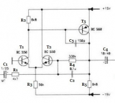
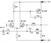
The integrator schematic for the low frequency range crossing over to mid range at 150Hz:

The mid range integrator for the range 150Hz to 1350Hz:

And the high range integrator for 1350 to 4000Hz:

So this is the early 90s solution. What is the assessment of this and how would a replacement by a "modern" OPA cicuit provide significant improvement?
Regards,
Winfried
The integrator schematic for the low frequency range crossing over to mid range at 150Hz:
The mid range integrator for the range 150Hz to 1350Hz:
And the high range integrator for 1350 to 4000Hz:
So this is the early 90s solution. What is the assessment of this and how would a replacement by a "modern" OPA cicuit provide significant improvement?
Regards,
Winfried
Attachments

If I understand correctly, the speaker has a accelerator attached to the VC or a separate coil to sens speaker position integrated with the VC? If this is true, then while you could probably do better with an OPA, I'd be pretty careful as you have a mechanical system in the feedback loop. Simulating that may be a challenge and you could end up with an oscillator. Possibly a full power oscillator.
Hi Mike,
thanks for sharing your concerns. I‘m well aware of the closed loop implications, yet, the Integrator is not inside the control loop, but „prepares“ the audio signal to be the reference for the sensor Signal comparison. It cannot cause Loop oscillation. The feedback loop uses an inductive sensor, so, instead of differentiating the sensor Signal, the input signal is integrated.
Greetings,
Winfried
.....So this is the early 90s solution.....
Very very good audio opamps were available and affordable in 1990. And an AC-coupled integrator does not need all the features you need to sell a million chips. I'm inclined to grant the Designer knew his/her stuff and respect that choice.
Also: this design is class A. That restricts the efficiency and output current. But when these are don't-care parameters, pure-A avoids any taint of crossover distortion. There have been only a few pure-A opamps, with short production lives. The jellybean transistor opamp is never obsolete or out of stock.
All that is required from this circuitry is to have negligible distortion when compared to the individual speaker drivers themselves... and I rather suspect that's the case even if the 3-transistor opamp isn't exactly the definition of a world-beater. Speaker drivers aren't exactly the last word in linearity, not today and even less so in 1990. You should just avoid anything with a (substantial) crossover distortion problem as mentioned, but that's rarely a major issue in line-level circuitry anyway.
Last edited:
Here's a quick AC simulation of the responses of the three circuits:

Low = Blue
Mid = Green
High = Red
I would say there's a bit more tuning to the drivers going on than what immediately meets the eye.
Low = Blue
Mid = Green
High = Red
I would say there's a bit more tuning to the drivers going on than what immediately meets the eye.
Hi and thanks for the initial response!
The integrator schematic for the low frequency range crossing over to mid range at 150Hz:...........
Thanks. So these simple circuits do in fact emulate a discrete opamp. It is basic but non the less effective.
Essentially the + input (non inverting) is grounded and the - input (inverting) is used as the input. Classic opamp configuration for an inverting gain stage. Gain at DC and LF is set by the ratio of R1 and R4.
Gain = R4/R1 and is inverting of phase.
The cap across the 330k modifies the AC response.
I don't know if you would gain anything by using an opamp... technically you would... audibly you may not. The distortions added by such a simple discrete stage may be part of the overall character of the unit.
- Home
- Amplifiers
- Solid State
- Transistor or OPA Integrator?