Hi all, I don't often visit here unless I need something😱. Thank goodness for the depth and breadth of our membership and their expertise, not to mention their patience.
I looked around for practical suggestions and projects on the topic but haven't found much here on the forum, other than theoretical discussion of design, rather than actual device noise problems. We are facing, if not already struggling, with a shrinking supply of genuine new production, reliable to specified quality, thru-hole semis for the more critical areas in low signal and line-level audio. At affordable prices/quantities, we are left with only a few complementary types, such as KSC1845/A992, BC550/560, 546/556 that meet most of our needs but for how long and at what prices in the future?
On the other hand, we are swamped with cheap copies, fakes and even some good BJTs too, out there but many are what I'd call popular types from 40 or more years ago - good enough for many general applications but doubtful and variable quality for audio. So what I'd like, is a simple amplifier that is set up for a direct audio test of small signal transistors, with a test socket, small loudspeaker on a baffle and maybe another socket for a DMM with bargraph scale to aid recording the results, as necessary.
We can do that pretty easily, even on a breadboard but for a more permanent arrangement, I hope to use FR4 matrix board and use the DUT like a buffer amplifier before an opamp, followed by a a small chipamp or perhaps just a low-power chipamp for both, such as LM386, TDA2822, TDA2030 and so on.
The question is; in what circuit, with what input arrangement, impedance, gain, bias etc. do we operate the transistor? It has to give a reasonable representation of how the transistor will sound in a typically sensitive application and that means, I think, the dominant popcorn and hiss noise of the input stage transistor, as a LTP or singleton.
I recently watched a video where a DIY had adapted his unstably high gain stomp-box amplifier and fitted it with a socket for the DUT - no circuit details. He was plugging and testing transistors at a great rate, with very obvious differences between individual, new transistors from apparently, the same lot. I was convinced that there would be useful results with this simple technique if applied to audio amplifiers too, given that many of us are tempted to use cheap semis and this test at least tells us just how bad the idea probably was
I'm really only interested here in qualitative testing because it goes without saying that it's quite appropriate for audio, with respect to SNR. Any support, suggestions for the test circuit, comments etc?
Using a speaker for device assessment or sorting is not that reliable but meters are. You could easily build an amp with a bandpass filter on its output to a meter for approximate noise measurements. A full tester would need to be adjustable for operating points and source impedance which adds a lot of complexity (I can send you the manual for a Quan-tech transistor noise analyzer to see what it needs) but probably more than needed. You would need different circuits for bipolar and jfets and n vs p devices. The other challenge is to correct for the different gain of different transistors. With feedback you may hide the devices noise so you want to run open loop, but low gain transistors will seem lower noise.
How far do you want to go with this?
How far do you want to go with this?
In a stomp box there might very little or no negative feedback at all so the individual transistor parameters are going to have big impact. In a design where the goal is not to produce distortion the individual transistor parameters will have lesser effect or no effect at all. I wouldn't waste my time rigging up some noise measuring set up for testing individual transistors because we already know how to design for low noise.
Using a speaker for device assessment or sorting is not that reliable but meters are. You could easily build an amp with a bandpass filter on its output to a meter for approximate noise measurements.
A full tester would need to be adjustable for operating points and source impedance which adds a lot of complexity (I can send you the manual for a Quan-tech transistor noise analyzer to see what it needs) but probably more than needed. You would need different circuits for bipolar and jfets and n vs p devices. The other challenge is to correct for the different gain of different transistors.
I agree with you so far. An alternative might be using two amplifiers, a voltage amplifier for noise voltage testing and a transimpedance amplifier for noise current testing.
With feedback you may hide the devices noise so you want to run open loop, but low gain transistors will seem lower noise.
This doesn't make sense to me. As long as you use the device under test as the input device, feedback can't hide any noise at all. Meanwhile it solves the gain difference issue. The trick is to keep it stable with different input devices.
In a stomp box there might very little or no negative feedback at all so the individual transistor parameters are going to have big impact. In a design where the goal is not to produce distortion the individual transistor parameters will have lesser effect or no effect at all. I wouldn't waste my time rigging up some noise measuring set up for testing individual transistors because we already know how to design for low noise.
This also doesn't make sense to me. If you know how to design for low noise, you know that base spreading resistance, hFE and the 1/f corner have a big impact, and those are all different depending on the transistor.
By the way, somewhere around 1994 I built a high-gain negative-feedback voltage amplifier for a noise optimization college demonstration. It had a bipolar input transistor driven from a capacitive source and you could change the collector current over a very large range. As you turned up the current, you first heard the white noise decrease and then the base shot noise filtered by the capacitive source increase. I must still have the schematic in the attic, I'll see if I can dig it up.
Last edited:
This also doesn't make sense to me. If you know how to design for low noise, you know that base spreading resistance, hFE and the 1/f corner have a big impact, and those are all different depending on the transistor.
If I plan to use ZTX851 the datasheet gives me pretty good clues what hFE and fT are going to be. Datasheet doesn't tell me the base spreading resistance but bunch on people on the internet do.
In Horrowitz-Hill, Art Of Electronics Rev 3
is both a measurement circuit and measured data of a lot of transistors.
You want that book anyway.
< Amazon.de : art of electronics >
is both a measurement circuit and measured data of a lot of transistors.
You want that book anyway.
< Amazon.de : art of electronics >
You are absolutely right gerhard, I do want the book but it's a little expensive with freight costs etc. I have the 2nd edition but I don't recall practical test gear getting so much attention there. I must check it again, anyway.
To clarify the OP, the noise character in question is audible output noise generated in discrete transistor input devices. In description of the noise at a moderate volume level with full-range loudspeakers, this can vary from virtual silence to irritating hiss with random crackles and pops, such as we all have heard and dislike.
As a comment on sourcing semis , when I have bought maybe 100 new, low noise transistors on cut tape from major US distributors , they seemed to all be very similar on most parameters, as you'd expect. there were maybe 10% that were noticeably worse on noise but fewer were much quieter than average. I had the same experience with taped KEC product 2SC945/A733 from a Taiwan seller.
A few times, I've bought bulk, factory-sealed packs of up to 1,000 transistors elsewhere - copies of 2SC1815 recently, as it happens. The distribution of noise (voltage, I think) level is clearly more like the statistical "bell curve" so I believe this has been genuine product, where smaller quantity purchases of such copied products have been inconsistent. Some have been picked over for high gain etc. and this affects the distribution of other properties too, so our suspicions of platform sellers or their sources can be justified.
I have bought a lot of transistors over many years, mostly to pass along in smaller quantities to others, at cost. The benefit to me is that I also get better prices and quality for my own projects. I have a bigger handle on what to expect from the product too but there is always a likelihood of being stuck with unpopular or off-spec product, if we push our luck when buying.
BTW, here's a link to the short but amusing video (no dialogue, so you can turn up the volume a little to hear the different noise components)
Test rumore dei Toshiba 2SC1815 per il Giovanetti HandWired TS-808 - YouTube
Test rumore dei Toshiba 2SC1815 per il Giovanetti HandWired TS-808 - YouTube
Last edited:
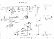
This is the demo circuit I wrote about in post #4. The bandwidth is limited to about 1 kHz on the lower side by the DC feedback loop and to about 40 kHz on the upper side by the output low-pass filter. The 21.5 nH inductor is a 1 cm-diameter loop made of the wires of the 4.7 ohm resistor.
Attachments
Ian Finch, thanks for the link, I will have to build that setup for testing and add PNP as well.
looks like LM386 gain=100 fed by transistor gain maxed out.
looks like LM386 gain=100 fed by transistor gain maxed out.
Hi stocktrader200. I'm not sure what version or sections of the Ibanez TS808 stompbox circuit were used in the video but for anyone with an interest, it seems that the design was common to all versions with only minor differences in the tone and effects stages. There is a good reference summary with schematics and descriptions here: History of the TubeScreamer TS808 Overdrive Effect Pedal | PuzzleSounds.
I'd only be guessing that you could just follow the input stage design there with an LM386 in an app-note type of circuit to make a similar test jig. I doubt it's that simple, since effort needs to go into more suitable band-limiting so that we can also take meaningful measurements.
Also, thanks to M. for finding and posting that interesting demo circuit. I guess it would also need modification to enable measurement of the full audio range.
caution, measuring the full audio range as a single number will be misleading. The spectral distribution won't be uniform so the LF stuff will dominate. You can use a PC spectrum/RTA to quantify the spectral distribution however. If the base/gate resistor can be switched between low (0 or 100) Ohms and high (10K and 100K Ohms) you can separate the voltage noise from the current noise. The other key elements that you would want to control/adjust are the collector/drain current and vCE or vSD since those also have a significant effect on the actual noise.
Ian, you may want to look at how Scott Reynolds went about his survey of noise performance testing for input stage valves at Tavish Design - there would be quite a few parallels. He also has a thread on DIYaudio somewhere:
Tavish Design
Tavish Design
Another way to evaluate device hiss. Not for production or documentation, but perfectly valid for DIY, if you use circuit and speakers/room similar to the final application.
Test rumore dei Toshiba 2SC1815 per il Giovanetti HandWired TS-808 - YouTube
Test rumore dei Toshiba 2SC1815 per il Giovanetti HandWired TS-808 - YouTube
- Home
- Design & Build
- Equipment & Tools
- Transistor noise assessment