I am driving some nixie tubes off of an arduino and some bjts. I am using A5T5058
transistors driven off the Arduino output pins. It works but is kind of dim. Can someone explain to me how to size the base resistors and the resistor on the 170volt supply line? See attached.
Thank you.
Jeff
transistors driven off the Arduino output pins. It works but is kind of dim. Can someone explain to me how to size the base resistors and the resistor on the 170volt supply line? See attached.
Thank you.
Jeff
Attachments
> nixie tubes .....It works but is kind of dim.
They are not LEDs. Dim may be OK. What if you short a transistor C-E so the full 170V is applied across the 33k and neon?
They are not LEDs. Dim may be OK. What if you short a transistor C-E so the full 170V is applied across the 33k and neon?
There was a dedicated BCD to Decimal driver for Nixies, the 74141
The fact that it is BCD means you can use the BCD library in arduino, and use less digital IO pins.
That high voltage transistor is quite old, a modern part with more gain is MPSA42 but this will work just fine.
A SN7442 will allow you to have less digital IO's on the arduino, and there is allready a function for BCD so you dont have to make a lookup table for binary to BCD yourself.
You can multiplex nixies like you would Leds, just at reduced frequency like 1Khz.
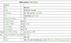
Also, your nixies are 140V holding current and 2.5-3.5mA normal operating current. at 170 in and 140 over the nixie you are now running them at about 1mA, I suggest using 10K or so for the anode resistor.
The fact that it is BCD means you can use the BCD library in arduino, and use less digital IO pins.
That high voltage transistor is quite old, a modern part with more gain is MPSA42 but this will work just fine.
A SN7442 will allow you to have less digital IO's on the arduino, and there is allready a function for BCD so you dont have to make a lookup table for binary to BCD yourself.
You can multiplex nixies like you would Leds, just at reduced frequency like 1Khz.
Also, your nixies are 140V holding current and 2.5-3.5mA normal operating current. at 170 in and 140 over the nixie you are now running them at about 1mA, I suggest using 10K or so for the anode resistor.
I am not concerned abotu the io pins being used up . I have an arduino mega dedicated to running 4 nixie tubes as a pair of 2 digit displays. So I have pins for days.
The datasheet says 7 volts for the base to emitter voltage. I am only using 5. How can I check to see if I am turning the transistor all the way on?
The datasheet says 7 volts for the base to emitter voltage. I am only using 5. How can I check to see if I am turning the transistor all the way on?
Actually the datasheet says you can damage the transistor when you apply more than 7 V in reverse, not that you need 7 V to turn it on. When the transistor is on, there will be about 0.8 V between base and emitter. The 3 kohm resistors then determine the base current. The base current has to be at least 1/hFE,min times the collector current for the transistor to saturate (work as a turned-on switch).
The collector current with saturated transistor is the high-voltage supply voltage minus the drop over the Nixie tube minus the collector-emitter saturation voltage of the transistor divided by 33 kohm. I guess that's about 2 mA, but I can't calculate it accurately as I don't know what the drop across the Nixie tube is.
Neglecting the drop across the microcontroller's output port, the base current is (5 V - 0.8 V)/3 kohm = 1.4 mA, so using hFE,min = 10, that should be enough.
Do you know what the maximum allowed current is for the Nixie tube?
By the way, you can check if the transistor is saturated by measuring its collector-emitter voltage. It should be below 1 V when the transistor is on.
Last edited:
I think we are missing the point here. the correct answer has allready been given. The neon nixies are gas tubes that strike at 165V and hold at 140V
This has nothing to do with the saturation characteristics of the transistor driver. That transistor is in saturation unless is has a Hfe liwer than ...15
The current limiting resistor is currently allowing for ~1mA of current wheras the normal operating range for the IN-12 is 2.5-3.5mA if we take 10-15K instead of 33K in series with the anode we get the right operating current
Mr Carlson has done a project like this on YouTube, it might be worth watching it to see what tricks he used.
I think we are missing the point here. the correct answer has allready been given. The neon nixies are gas tubes that strike at 165V and hold at 140V
If the maintaining voltage is indeed 140 V (I can't read Russian datasheets), then you are right - I had overlooked the last sentence of post #3. I think 170 V nominal supply voltage is rather tight when the striking voltage is nominally 165 V anyway.
- Home
- Design & Build
- Construction Tips
- Transistor help needed