Hi
Im working on some simulations in the Simetrix software. Basically, i want to input a basic 1Khz sinewave into a Fuzz Face/trans fuzz circuit sim to show the effect of transistor saturation (for some presentation work) However, ive come across some problems (mostly, my knowlege is not extensive enough to finish the circuit - ill post an image)
So, following this, does anyone:
1 - know how to finish the circuit off so i can get an output?
2 - OR have some waveform images of the effects of the transistor saturation?
thanks in advance. 😱
Attachments
So, following this, does anyone:
1 - know how to finish the circuit off so i can get an output?
2 - OR have some waveform images of the effects of the transistor saturation?
thanks in advance. 😱
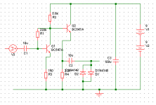
1 - The input voltage needs to be grounded, and you need to put a load on the output that you want to measure to ground as well, say 100k. First generate the waveform by >> Simulator > Choose Analysis > Transient > Run. Then >> Probe > Voltage, place the probe icon on the node that you want to see and click on it - a graph should be generated.
2 - Not transistor, but using an opamp, same idea though... see http://gaussmarkov.net/ltspice/DOD250%20-%20clipping.png
Jaz
Last edited:
That circuit will show the effect of diode clipping, not transistor saturation.Basically, i want to input a basic 1Khz sinewave into a Fuzz Face/trans fuzz circuit sim to show the effect of transistor saturation
In your latest circuit you forgot to connect Q2's collector. Otherwise it looks OK.Any clues?
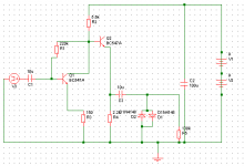
Have you got V3 set up right? You need to set wave shape = sine, frequency = 1K, offset = 0, Amplitude = whatever. Try different amplitudes. I got the outputs below with 20mV, 50mV and 100mV.
If you're not getting anything sensible, maybe you're not setting up the analysis right. Here's what you need to do:
- From the menu bar, go to "Simulator" => "Choose Analysis..."
- Set Analysis mode = Transient
- Go to the "Transient" tab
- Set Stop time = 5m (so you can see a few waveforms)
- Click on "Advanced options" and set Max time step = 10u (the default is always much too high)
🙂
Attachments

Hi Jaz,
double thanks!
However, ive still had a few issues with Simetrix...V1&V2 shorted voltages...Not a clue where im going wrong after following your advice. Any clues?
thanks again😕
There are nets shorting out each V1 and V2, you can see the green trace running vertically right through the center of each of these sources, just delete these traces.
Thanks
-Antonio

Cheers guys - all sorted - got some weird results - doesn't look like clipping, more an uneven form of saturation maybe? weird...
Well one side is completely clipped, try shifting the bias a bit to see if you can get it a bit more symmetrical (not fully, that won't sound so good). Head on over to diystompboxes.com, where a lot of experienced pedal builders hang out, you will pick up a lot interesting ideas there.
Jaz
- Status
- Not open for further replies.
- Home
- Design & Build
- Software Tools
- Transistor Fuzz Simulations - Simetrix