also i think a 10k resistor between q17 base and ground should set the relay (after some delay). if it does the trick then there's some open circuit there.
You may have several versions of schematic, but do more than one agree with the relay circuit? The preamp, signal path, power amp, and power supply are probably working, so all we need is a good schematic of just the relay part.
Hi Kirchhoff
you analysis is correct, with 10k to earth from base of Q17, a small delay then the relay clicks in. I will try and extend the diagram to include all the relay components and post
thanks again
you analysis is correct, with 10k to earth from base of Q17, a small delay then the relay clicks in. I will try and extend the diagram to include all the relay components and post
thanks again
hi
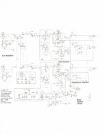
attached circuit is from the unit, apologies about the quality even the original is very hard to read.
Also updated relay circuit, with everything that appears to pertain to the relay- C61 is part of the power supply circuit and the 2.2m resistor and diode heads off and goes to a daughter board and appears to be B+ at 15.6 volts
thanks
Attachments
Hi Kirchhoff
you analysis is correct, with 10k to earth from base of Q17, a small delay then the relay clicks in. I will try and extend the diagram to include all the relay components and post
thanks again
Ok, then either the 20V voltage is too low or the output from the 7818 is too high. or some component is off. Can you measure and post the voltages you have:
- at the 20V supply
- at both ends of the 10k resistor installed in q17 base circuit
- q17 emitter
- at the output of the 7818 directly on its pin
be precise to the second decimal, it matters.
P.s. you're very close to the solution, don't give up.
Last edited:
Hi
so -
The 20v supply is 20.3V
with the 10k connected between base and collector of Q17-
the voltage at the base end of the 10k is 17.75v
the voltage at the collector end of the 10k is 18.05v
the emitter of Q17 is 18.43
the output of the 7818 is 17.95v
the relay pin that connects to Q19 collector is 1.01v and the other connector is 19.95v
no plans on giving up- I am very curious and would like to understand the principles as well as solve the problem
thanks again
Vbe is 0.3Vbe. That transistor is not turned onHi
so -
The 20v supply is 20.3V
with the 10k connected between base and collector of Q17-
the voltage at the base end of the 10k is 17.75v
the voltage at the collector end of the 10k is 18.05v
I'm not following your whole story. Can you plot your voltages on the sch and re-post?the emitter of Q17 is 18.43
the output of the 7818 is 17.95v
the relay pin that connects to Q19 collector is 1.01v and the other connector is 19.95v
no plans on giving up- I am very curious and would like to understand the principles as well as solve the problem
thanks again
The switching transistor must be "saturated" when turned ON.
That requires the base current : emitter current ratio to be higher than 1:20. and preferably >1:10
This requires the base current to be ~ 10% of the relay current.
Allow a bit for the 1k8 (~0.35mA)
That requires the current down through the trigger transistor to CHANGE by {relay current/10 + 0.35mA}
The sch as drawn cannot achieve this.
The switching transistor must be saturated to allow it to operate fairly cool and to allow sufficient voltage to reach the relay.
Vbe sat ~0.75V to 0.9V, when Ib ~ Ie/10
Vce sat ~0.03V to 0.1V, when Ib ~ Ie/10
These values are quite different from unsaturated operation.
A 100mA 300mW small signal transistor can operate as a switch for relays that draw upto 40mA at their rated voltage. AND their hFE can be very low, even as low as 25, because you will run it saturated.
Last edited:
Vbe is 0.3Vbe. That transistor is not turned onI'm not following your whole story.
Seems like this is the issue. Plus, connecting 10k from base to ground will turn it on (as tested by OP).
So let's concentrate on Q17 and supporting components.
As I understand it from the manual and hand drawn schematic, it compares a stabilized 18V (7818), with an unstabilized 20V or so. With the purpose that, if the power (110V) drops below a certain threshold, so will do the 20V and Q17 will turn off.
In normal state it should be ON, providing base current to the next transistor.
At this point I'm suspecting some component is degraded (diode, 2.2k and 10k, transistor) or a poor solder joint.
Here's an experiment you can do to try to understand which is which:
-remove any additional components you may previously have added yourself
- take a 10k resistor, solder some wire to its ends, and solder the wires directly to: 1) Q17 base at one end 2) 18V output pin of 7818 at the other end.
This would help bypass the original 10k resistor and any problems associated with it (solder joints / pcb trace fractures).
Let us know if it works like this.
Last edited:
Hi
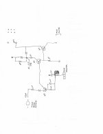
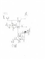
I have attached a circuit with additional voltages, which I hope is readable.
I have market point A which is the Q18 collector side of the 12k resistor- when I put a meter across this the relay trips to off, yet when I measure the collector of Q18 directly the relay stays on- I have checked the continuity of the PCB track here and it is OK- and I have sat staring at the PCB with a magnifying glass and can not see any breaks/lifted track etc. I have also checked the continuity and all seems fine.
all transistors, diodes, capacitors and resistors have been replaced with the exception of the 2.2k on the 20v rail
so if Q17 if not switching on- which seems the case- then perhaps I should put in another 2n3906 and see if the transistor (although new) is the problem.
I will also resolder all the connections
I will do the 10k resistor replacement as Kirchoff suggests later today and report back
Thanks again- I am learning stuff!
Attachments
Hi
removed the 10k and 10uf cap between the 7815 and Q17 base and soldered a 10k directly between the output of the 7815 and the base of Q17. The relay does not operate
removed the 10k and 10uf cap between the 7815 and Q17 base and soldered a 10k directly between the output of the 7815 and the base of Q17. The relay does not operate
Hi
removed the 10k and 10uf cap between the 7815 and Q17 base and soldered a 10k directly between the output of the 7815 and the base of Q17. The relay does not operate
Something's amiss. You should have around 9V on Q17 base and collector.
OK. Let's try something different. With all original components in place, add a 10k resistor in parallel to the one between the base and collector of Q17. This should help to turn the transistor on. If no workie, try a smaller resistor - let's say 4.7k.
Then repeat the process, this time across the resistor between the base of Q17 and the 7818.
Let us know which particular combination (if any) did turn on Q17 / set the relay.
The trigger transistor must allow the switching transistor to become saturated when the relay is to be active.
If the relay passes 30mA then the base current of the switching transistor msut be at least 2mA and preferably 3mA.
This 3mA has to come from the trigger transistor.
If there is a 10k in the feed to the trigger transistor, how can it pass 3mA to the switcher?
Draw a simple two transistor trigger/switcher to a relay.
See where the currents NEED to FLOW.
Hi
I have attached a circuit with additional voltages, which I hope is readable.
I have market point A which is the Q18 collector side of the 12k resistor- when I put a meter across this the relay trips to off, yet when I measure the collector of Q18 directly the relay stays on- I have checked the continuity of the PCB track here and it is OK- and I have sat staring at the PCB with a magnifying glass and can not see any breaks/lifted track etc. I have also checked the continuity and all seems fine.
all transistors, diodes, capacitors and resistors have been replaced with the exception of the 2.2k on the 20v rail
so if Q17 if not switching on- which seems the case- then perhaps I should put in another 2n3906 and see if the transistor (although new) is the problem.
I will also resolder all the connections
I will do the 10k resistor replacement as Kirchoff suggests later today and report back
Thanks again- I am learning stuff!
2M2 is too high resistance for Q18 collector side. A reading mistake ?
Probably the big capacitor after the bridge rectifier has dried out.After all, only 20V to feed a 7818 is to low.The voltage difference before and after the 7818, what turns on Q17 is to small.
Mona
Mona
Thanks all for the assistance, so in no particular order:
the 2M2 is the correct value
All the electolytics have been replaced, so no dried out cap, however I did decide to measure the AC coming off the transformer and it is 36V AC- which then feeds a W04M (new) and produces the 20.3V - which may be too low to switch Q17 on
Andrew thanks- can I just check my understanding-
Q17 senses the unregulated voltage (20.3) and the regulated voltage (7818-17.95v) and turns on Q18 if the difference is correct (which it appears it is not)
Q18 is the trigger transistor, which when turned on by Q17 then saturates Q19 and this fires the relay.
I will try and draw the trigger circuit as you suggest, as this is new territory for me, and I greatly appreciate the patience and knowledge
thanks again
By 36V ac you mean 2x18V ac .Ones rectified the voltage becomes 18x1.4 minus the drop on the diodebridge, total rond 24V. So the 20V isn't right.If the capacitors are new there are tree other causes possible, bad bridge or the rest of the circuit draws to much current or wrong capacitor value.
Mona
Mona
The transformer is center tapped, so 36v measured at the input to the bridge.- I got 22.8v DC from an online calculator as the estimated DC- The 20v is prior to any capacitors, I will try swapping out the bridge- thanks!
- Status
- Not open for further replies.
- Home
- Amplifiers
- Solid State
- transistor and relay problem