Don't do anything that makes you uncomfortable. When weirdness occurs you'll immediately blame the not-comfortable piece, rightly or wrongly. Murphy's Law says: wrongly.
The ZTX851 is quite interesting. The noise is not specified on the datasheet BUT 20A peak and 5A continuous in a TO92? My concern is that usually low noise transistors have some process parameters closely watched that are less important for power devices or so I have been told.
Don’t worry, all power devices are low-ish noise, that’s the physics. The ZTX851 and its complementary are high current switching devices, no need to put them in a power device casing.
The ZTX851 is quite interesting. The noise is not specified on the datasheet BUT 20A peak and 5A continuous in a TO92? My concern is that usually low noise transistors have some process parameters closely watched that are less important for power devices or so I have been told.
ZXTN2018FTA in SOT-23 works just as good.
Funny enough, it has the SMD-marking "851" which might mean something.
That was for a chopper amplifier test in the 10s of KHz, where the
capacitor size problem collapses.
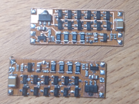
Attachments
Had a look at mine - so it does! I guess its the same die, less power handling, I measure it as about 1.4dB above my 0.5nV floor which is what you'd expect for an '851ZXTN2018FTA in SOT-23 works just as good.
Funny enough, it has the SMD-marking "851" which might mean something.
I just ran across this in another forum and thought I should share it for ideas: https://arxiv.org/pdf/1708.06311.pdf from DIY nanovoltmeters and ultra low frequency noise preamplifiers, who did it? - Page 1 The target application (cryogenic measurements) is a little different from audio but the basics are still there.
I would have done some of it differently but generally with the same goals.
I would have done some of it differently but generally with the same goals.
Fascinating equipment they design and use!
Interesting way to protect the inputs:
"A dedicated circuit protects the first amplification
stage: A junction FET with an impedance of 5 Ω is connected in series to each input. At a voltage drop of about
10 mV over the FET the protection circuit starts to oscillate. The alternating signal is amplified by a transformer and then rectified. This signal pinches off the
FET. Together with consecutive protection diodes, this
circuit protects the sensitive components against overvoltages up to ±20 V at the input."
No, I didn't. I have mainly used the amplifier to measure noise from voltage regulators, so current noise was not a major concern. But I will try to measure it.
I finally got around to measuring the current noise.
I measured a current noise of around 3.25pA/rtHz. As long as the source resistance is below a few hundred ohm, the thermal noise from the source will be more important than the current noise.
- Home
- Design & Build
- Equipment & Tools
- Transistor and opamp noise floor measurement amp