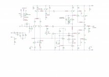
Building a 30 watt class A amplifier using the attached LTSpice schematic and pcb layout. I have the prototype board set up on the test bench with a GW Instek GPE3323 regulated power supply, an OWON HDS242S for the scope and signal, and an OWON XDM1041 bench multi-meter.
First I tested without the output transistors installed. Power supply set to +/- 32 volts DC. The ground reference for signal and power are connected floating to the common of the power supply. All voltages at every node match the simulation results of the LTSpice run. With a 2Vpp signal I adjusted the bias to correspond with the voltage gain shown in the LTSpice run. All input signal voltage changes from 0.5Vpp to 2.6Vpp (clipping) thereafter matched and followed the corresponding LTSpice runs for signal gain. So far so good.
Connecting the output transistors (heat sinked plus fan), I adjusted the bias to 1.3 amps and the board ran at idle without issue over two hours, maintaining the bias current exactly at 1.3 amps. However, when I went to do a signal test and attached the signal generator lead to the pcb input, the power supply tripped at the cutoff current I set at 1.5 amps. Setting the current limit to the 3 amp max, the power supply still tripped and ran at constant voltage (about 5 volts).
No matter what I touch to the input node -- probe, rca cable, even a piece of wire -- the current draw increases (seems like it's shorting out somewhere). I even hooked up an rca cable from a cd player. Same thing, tripping the power supply.
I tried installing a 100K resistor between the signal input and ground upstream of the capacitor and removing the input capacitors. I tried tying the ground from the power supply common to the earth ground. Nothing changed.
I built another type of transistor amplifier using the same power supply and it works just fine. Never had the above issue while testing that one.
Appreciate any suggestions,
thank you
thanks


Last edited:
Hi George!
Try to remove C5 and put in parallel with R6. Remove R19 and connect C4 to collector of Q6.
Try to remove C5 and put in parallel with R6. Remove R19 and connect C4 to collector of Q6.