Hi. First, thank you for reading my post.
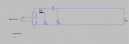
I am learning how to use LTspice . Here is a simple bridge rectifier/smoothing circuit below, along with the .asc file. Transient analysis is roughly matching what my calculator spat out, but I am getting 0V DC opperating point on every node
 . I assume I have made a simple mistake or have a missing Spice directive?
Any help, adivce would be greatly appreciated.

View attachment Filtered DC.asc
I am learning how to use LTspice
 . Here is a simple bridge rectifier/smoothing circuit below, along with the .asc file. Transient analysis is roughly matching what my calculator spat out, but I am getting 0V DC opperating point on every node
Any help, adivce would be greatly appreciated.

View attachment Filtered DC.asc
Last edited:
Ah, I think i see... so the spice sim will not simulate rectification? I need to add a parallel DC source ?
Spice doesn't know its a rectifier - how can it? A rectifier is not a DC source - it only approximates a DC source eventually. The .op function examines the circuit at t=0, and the output of a rectifier at that moment is zero.
You have it right there in your schematic - the .trans function should show you all you need to know. Run it long enough and the output will stabilize at some ripply average value, but its still not DC.
You have it right there in your schematic - the .trans function should show you all you need to know. Run it long enough and the output will stabilize at some ripply average value, but its still not DC.
The 'startup' option prevents spice from even doing a DC solution prior to the transient analysis, so when you probe a node there is no steady state DC value to give you.
Note that if you want to stay within the .op domain (why?.?), you can add a phase shift to your sine input source: with 90° you will be close to the actual working voltageAh, I think i see... so the spice sim will not simulate rectification? I need to add a parallel DC source ?
- Status
- Not open for further replies.