New transformer?
Hi.
I'm afraid there is no hope,unless you want to rip out the windings and ruin the whole thing.
There is a method to get a positive and negative supply from a
single winding, but I don't recomend it.
Regards.🙂
Hi.
I'm afraid there is no hope,unless you want to rip out the windings and ruin the whole thing.
There is a method to get a positive and negative supply from a
single winding, but I don't recomend it.
Regards.🙂
Dj,
How many T2 transformers do you have, what is this power and how much power do you need from it?
How many T2 transformers do you have, what is this power and how much power do you need from it?
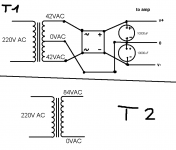
it is 1600VA transformer of 84~0 VAC
and i need 1600VA transformer of 42~0~42VAC
and i have one of "T2"
and i need 1600VA transformer of 42~0~42VAC
and i have one of "T2"
Nobody has asked the most important question, that is:
what type of transformer is it? If it's a toroidal and not potted it could be doable assuming you know what you are doing. An EI core is alot more work.
A 1600VA 84V transformer is just about the most useless thing I can think of. So you may as well give it a try because you are probably never going to use that sucker for anything else.
Dj,
Since you have just one, the best thing to do is to rewind the secondary to achieve what you want.
If you don´t have enough skills to do it you can try eletric motor repair shops. Toroidal cores are worse to modify.
The second option would be to use two step-down switching converters, one of them inverting the output. But it will be a little bit more complicated and I don´t know if it is more expensive than a new transformer or not.
Regards,
Just build a bridge amp with it. You only need one supply rail for that , and only one filter cap.
A Crown Macrotech 2400 uses this same voltage and VA rating, 800W4R and 1200W2R.
A Crown Macrotech 2400 uses this same voltage and VA rating, 800W4R and 1200W2R.
DJK,
The Crown Macrotech uses a totally different topology than what you describe. The man is confused enough as is. The controller for that circuit is rather complicated. Yep, I know, I just repaired it's little brother today, a Power base 2. Almost the identical controller, same topology. LOVE those amps especially the 3600.....
Chris
"The Crown Macrotech uses a totally different topology than what you describe."
The Power Base 1, 2, 3, and the Power Tech, Micro Tech, Macro Tech, and Com Tech all use the identical circuit boards.
The PB1 has one pair of outputs per bridge half, the PB2 has two pair of outputs per bridge half, the PB3 has three pair of outputs per bridge half.
IOW the PB1 has two pair of outputs missing, the PB2 has one pair of outputs missing, the PB3 is all full up.
All are powered by a single voltage for the outputs, about 80V, 100V, 120V.
The fan has a transformer winding in it to provide ±15V regulated for opamps on the PIP modules.
The only ground current flowing is in the µA region for the diff inputs or less for the opamps.
No center tap on the high current supply for the outputs is needed.
djk said:"The Crown Macrotech uses a totally different topology than what you describe."
The Power Base 1, 2, 3, and the Power Tech, Micro Tech, Macro Tech, and Com Tech all use the identical circuit boards.
The PB1 has one pair of outputs per bridge half, the PB2 has two pair of outputs per bridge half, the PB3 has three pair of outputs per bridge half.
IOW the PB1 has two pair of outputs missing, the PB2 has one pair of outputs missing, the PB3 is all full up.
All are powered by a single voltage for the outputs, about 80V, 100V, 120V.
The fan has a transformer winding in it to provide ±15V regulated for opamps on the PIP modules.
The only ground current flowing is in the µA region for the diff inputs or less for the opamps.
No center tap on the high current supply for the outputs is needed.
First of all you should get that Crown circuit to see how they do it: convert single supplies into dual supplies without a transformer or using a virtual ground on a high current amp.
As far as I know it can't be done without doing any of that. But maybe there's a third way that I don't know about and would love to.
Second: you can still use that transformer, as long as you put a capacitor at the output. Not a very good option, but the only one I can think of.
Third: those voltages you named (80, 100, 120) look like AC input options, not output voltages. Is that so?
Carlos
Dude, I have all of the Crown circuits.... Which one do you need? I don't claim to know all about it but I know it isn't a simple process.
Good luck,
Chris
Good luck,
Chris
maybe an OTL amp is in need?
If you absolutely have to use the transformer, go find a book / schematics on how to power op amps from one source and do the same with your amp.
Yeah, you will have to have a large cap on the output to filter out the 1/2 Vdd.
If you absolutely have to use the transformer, go find a book / schematics on how to power op amps from one source and do the same with your amp.
Yeah, you will have to have a large cap on the output to filter out the 1/2 Vdd.
"The Crown Macrotech uses a totally different topology than what you describe. The man is confused enough as is. The controller for that circuit is rather complicated. "
http://www.delphion.com/cgi-bin/viewpat.cmd/US03808545__
Looks simple enough to me, the blocks marked 10, 12, 14, 16 are the output and driver transistors. The triangle marked 28 can be replaced by an opamp, it only has to drive the ±3V or so to drive 10 and 12 into full conduction. A person with a sharp eye will see that the left side of the bridge is the same as the Transnova design. The right side of the bridge is an ordinary amplifier, the opamp section has to swing the full voltage of the power supply, item 22.
As we can see, this IS a very simple concept.
"All are powered by a single voltage for the outputs, about 80V, 100V, 120V."
Item 22
"The fan has a transformer winding in it to provide ±15V regulated for opamps "
This provides power for item 28
"The only ground current flowing is in the µA region for the diff inputs or less for the opamps."
Items 34 and 37
"No center tap on the high current supply for the outputs is needed. "
Node 19 is a reference point, no high current flows through it.
"First of all you should get that Crown circuit to see how they do it: convert single supplies into dual supplies without a transformer or using a virtual ground on a high current amp. "
As we can see the just use it as a single supply.
"As far as I know it can't be done without doing any of that. But maybe there's a third way that I don't know about and would love to. "
See the patent.
"Second: you can still use that transformer, as long as you put a capacitor at the output. Not a very good option, but the only one I can think of."
Waste of time and money.
"Third: those voltages you named (80, 100, 120) look like AC input options, not output voltages. Is that so?"
No, that is the single B+ voltage used in a Crown Macrotech 600, 1200, and 2400 respectively.
As I am not a subscriber I couldn't see the patent details.
But of course I forgot there was a third way to do this thing which was bridging.
By bridging you float your (-) terminal from ground, as you invert the phase from the second amp and feed it as (-) to the speaker.
I don't see what Crown can patent for such a thing or why it was accepted. But as the US patent service already accepted zobel terminals as something that could be secured on some cable brands, you can see why.
Carlos
"I don't see what Crown can patent for such a thing or why it was accepted. But as the US patent service already accepted zobel terminals as something that could be secured on some cable brands, you can see why."
A patent is issued for something new.
An old idea used in a different way can qualify as 'new', MIT cables are an example of that.
Many newer amplifiers lack the damped output coil and thus have problems with weird cables, piezo tweeters, and elecrostatic speakers.
Adding little boxes on each end of the speaker cables with the parts that SHOULD have been in the amplifier is a 'new' idea.
A bridge amp is not new, but one that can have one speaker output grounded IS. Note the date as well: 1972
I linked to the IBM site so (hopefully) the front page picture shows up. Go to the USPTO site to view the details for free.
http://164.195.100.11/netahtml/srchnum.htm
Enter the patent number, go to the text page. To view images you need a free TIFF viewer:
AlternaTIFF: http://www.alternatiff.com/
Then you can click on 'Images' from the text page.
djk said:
A patent is issued for something new.
An old idea used in a different way can qualify as 'new', MIT cables are an example of that.
Many newer amplifiers lack the damped output coil and thus have problems with weird cables, piezo tweeters, and elecrostatic speakers.
Adding little boxes on each end of the speaker cables with the parts that SHOULD have been in the amplifier is a 'new' idea.
Maybe the interpretation of what is really "new" is in order here.
MIT is one example of what I'm talking about. It's absolutely ridiculous that something that was already being used before their register, like the zobel, could be accepted as such. MIT only took the zobel out of the amp or speaker end. Registering at the same time any filtering that could be done on the cable. Ridiculous!
But patents is not a matter that really interests me, as a patent is as good as your patent lawyer.
One thing I find amazing is the long time a patent or intellectual right of any kind is issued for. Particularly when such rights go to family, as if they were a house.
An invention is a discovery that belongs to society and after some time prizing the person who had the idea (based on all the knowledge that society put into him through school years), say like 15 years or so, it should automatically go to public knowledge. Renovation of a patent should be forbidden.
In any case, as I said, this is not a matter that really deserves my interest.
Carlos
"MIT is one example of what I'm talking about. It's absolutely ridiculous that something that was already being used before their register, like the zobel, could be accepted as such. MIT only took the zobel out of the amp or speaker end. Registering at the same time any filtering that could be done on the cable. Ridiculous!"
MIT is a cable manufacturer. They are correcting a defect in an amplifier. You wouldn't consider it 'Ridiculous!' if your amplifier blew up time after time when driving an electrostatic speaker, and the MIT cables fixed this.
"An invention is a discovery that belongs to society and after some time prizing the person who had the idea (based on all the knowledge that society put into him through school years), say like 15 years or so, it should automatically go to public knowledge. Renovation of a patent should be forbidden."
You can be excused for your ignorance of US law as you are not a US resident, a patent runs for 17 years. You are confusing it with a copyright, a different matter.
Technology obsoletes most patents long before they expire.
- Status
- Not open for further replies.
- Home
- Amplifiers
- Solid State
- Transfrmer problam !