Hi,
I was recently looking at
Marcel van de Gevel's
'Simple loudspeaker correction filters'
Linear Audio , Volume 2, pages 115-140.
Linear Audio | your tech audio resource
The proposed circuits are intended to use less capacitors and of more standard value than those used by the famous Linkwitz's tranform biquad circuit.
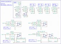
It reminded me that I once saw this kind of simple correction and found that in fact, I even simulated it a bit. I could unearth the corresponding Tina file which was buried in my archives since december 2008. I then did some redraw and here are four transforming high pass filters :
[circuit #1] fo = 1 kHz, Qo = 0.5 -> fp = 2 kHz, Qp = 0.5
[circuit #2] fo = 1 kHz, Qo = 0.5 -> fp = 4 kHz, Qp = 0.5
[circuit #3] fo = 1 kHz, Qo = 0.707 -> fp = 2 kHz, Qp = 0.707
[circuit #4] fo = 1 kHz, Qo = 05 -> fp = 0.5 kHz, Qp = 0.5
Has somebody an idea where I could have seen these circuits ?
PS: let's mention the existence of still other circuits which can be exploited to get similar functions.
I was recently looking at
Marcel van de Gevel's
'Simple loudspeaker correction filters'
Linear Audio , Volume 2, pages 115-140.
Linear Audio | your tech audio resource
The proposed circuits are intended to use less capacitors and of more standard value than those used by the famous Linkwitz's tranform biquad circuit.
It reminded me that I once saw this kind of simple correction and found that in fact, I even simulated it a bit. I could unearth the corresponding Tina file which was buried in my archives since december 2008. I then did some redraw and here are four transforming high pass filters :
[circuit #1] fo = 1 kHz, Qo = 0.5 -> fp = 2 kHz, Qp = 0.5
[circuit #2] fo = 1 kHz, Qo = 0.5 -> fp = 4 kHz, Qp = 0.5
[circuit #3] fo = 1 kHz, Qo = 0.707 -> fp = 2 kHz, Qp = 0.707
[circuit #4] fo = 1 kHz, Qo = 05 -> fp = 0.5 kHz, Qp = 0.5
Has somebody an idea where I could have seen these circuits ?
PS: let's mention the existence of still other circuits which can be exploited to get similar functions.
Attachments
OK, so apparently I've been reinventing the wheel again...
Anyway, I don't know if this helps, but there is an interesting article in Linear Audio volume 3 by Steven van Raalte, "Correcting transducer response with an inverse resonance filter", presenting a general Sallen and Key biquad. Actually it is not quite as general as it could be, because the amplifier gain is fixed to unity. Steven van Raalte uses three capacitors to fix two poles and two zeroes. He refers to an old textbook in German, Prof. Dr. Ing. Rolf Unbehauen & Prof. Dr. Ing. Albert Verlag, Netzwerksynthese in Beispielen, Band II, Passive und aktive RC-Netzwerke, RLC-Zweitore und Approximation, Oldenbourg Verlag, 1977, ISBN 3-486-21571-X.
Anyway, I don't know if this helps, but there is an interesting article in Linear Audio volume 3 by Steven van Raalte, "Correcting transducer response with an inverse resonance filter", presenting a general Sallen and Key biquad. Actually it is not quite as general as it could be, because the amplifier gain is fixed to unity. Steven van Raalte uses three capacitors to fix two poles and two zeroes. He refers to an old textbook in German, Prof. Dr. Ing. Rolf Unbehauen & Prof. Dr. Ing. Albert Verlag, Netzwerksynthese in Beispielen, Band II, Passive und aktive RC-Netzwerke, RLC-Zweitore und Approximation, Oldenbourg Verlag, 1977, ISBN 3-486-21571-X.
I've been using "degenerated" SK-filters for quite some time now but never saw a reference until now (yeah, reinventing the wheel). I do design them empirically using the correction target found as required/measured. This correction function I try to implement with the simplest possible circuit design (yet not too component value sensitive, a problem with SK filters in general). A optimizer is quite useful to speed up the process once your getting near the target response.
Hello KSTR,
What software do you use for optimization your active circuits?
Mit freundlichem Grüss,
Eelco
What software do you use for optimization your active circuits?
Mit freundlichem Grüss,
Eelco
LSPcad, professional version. The schematic editor is a bit awkward but for smaller building blocks it is very OK. Also, no elaborate OpAmp model.What software do you use for optimization your active circuits?
Finetuning is then done with LTspice.
This schematics changed my mind about the circuits to implement transforms :
https://jipihorn.files.wordpress.com/2013/06/linkwitz-variable-state.pdf
It was published by Jipihorn, a guy who had a very successful video-blog in french :
https://jipihorn.wordpress.com/2013/06/03/linkwitz-et-filtre-a-variable-detat-mise-en-oeuvre/
I analysed the principle of this schematic based on state variables circuits as follows.
The upper part contains a second order high-pass filter having the same parameters fo, Qo, of the driver in closed box to be transformed.
This high-pass filter is inserted in the negative feedback loop of an op-amp. The resulting response is the inverse of the high-pass filter. The driver is now flat but its diaphragm excursion becomes huge at very low frequencies (muliplied by 4 for each octave down).
So, to limit the excursion, the lower part introduces a new high-pass having the final parameters intended by the transform, ft, Qt.
It may look as this is a lot of op-amps to achieve a transform but this one is entirely configurable with no interference between the different settings.
I built a prototype with junk box components (JRC4560 and 10 kOhm, 5%, resistors) to check the noise :
I had to put my ear at less than an inch from my 94 dB/m/2.83 tweeter to hear it.
^ Interesting approach. With LF444MD/883 opamps it's going to be quite expensive, though ;-)
Did you check headroom at the indivdual opamp outputs? I have a feeling this circuit might suffer from lack of headroom / excessive local gain. This is a common problem with many circuits which is seldom discussed in textbooks.
Did you check headroom at the indivdual opamp outputs? I have a feeling this circuit might suffer from lack of headroom / excessive local gain. This is a common problem with many circuits which is seldom discussed in textbooks.
They were used only because Jipi had them at hand. The ubiquitous NE5532 would work perfectly in this application.^ Interesting approach. With LF444MD/883 opamps it's going to be quite expensive, though ;-)
I did not check headroom. Where can it happen ?Did you check headroom at the indivdual opamp outputs? I have a feeling this circuit might suffer from lack of headroom / excessive local gain. This is a common problem with many circuits which is seldom discussed in textbooks.
You can check with AC simulation if you find any spots that could be problematic, but also check with time domain signals how much overshoot etc is present at the output pins. Also input common mode range often need a check (less so with inverting stages).I did not check headroom. Where can it happen ?
A typical example where this consideration is very important is SK notch/dip filters (gyrator based) with moderate/high Q. Fliege filters (as per textbook) are a second example, the second opamp runs with a higher gain for most part of the signal while the circuit gain low (unity, typically), this time low Q values being the most problematic. GIC filters can be very probelamatic as well. I have little experience with state-variable filters, though. In general I would be cautions of any filter topology other than single opamp biquad (SK and MFB) when it comes to available headroom.
Hello KSTR,
Why is headroom also an issue when Gyrator notch circuits are applied? For boosting it is obvious, but for a ,let's say 10 db cut with a Q of 3 at 3 kHz, I am afraid I do not understand the problem. Would you be so kind as to explain the matter a bit further?
Kind regards,
Eelco
Why is headroom also an issue when Gyrator notch circuits are applied? For boosting it is obvious, but for a ,let's say 10 db cut with a Q of 3 at 3 kHz, I am afraid I do not understand the problem. Would you be so kind as to explain the matter a bit further?
Kind regards,
Eelco
A gyrator notch/dip structurally is a Sallen-Key 2nd order highpass with a source resistance. The output of the circuit is a tap somewhere along that source resistance. If the resulting highpass Q is large (like > 2) then you can have issues of the opamp ouput running into clipping and/or the input common mode range exceeded. Therefore some care is needed to avoid that by re-dimensioning the thing until the highpass-Q is lowest for a given target (notch Q and depth).
Rearranging for active inductor instead of standard gyrator suffers the same problem (opamp output is still a highpass) and has other issues (large opamp output current), but the slight advantage that the region above notch has the exact same gain as the region below, while the gyrator style circuit always has a bit lower gain above the notch. For real filters this is only of academic interest therefore the normal gyrator circuit is the standard choice.
Rearranging for active inductor instead of standard gyrator suffers the same problem (opamp output is still a highpass) and has other issues (large opamp output current), but the slight advantage that the region above notch has the exact same gain as the region below, while the gyrator style circuit always has a bit lower gain above the notch. For real filters this is only of academic interest therefore the normal gyrator circuit is the standard choice.
- Status
- Not open for further replies.
- Home
- Source & Line
- Analog Line Level
- Transforms using Sallen and Key topology