Festive greetings to one and All,
I was hoping someone could throw some pearls in my direction...
One point Nelson made about driving larger Vfets is that they need more gate current if you wanted to retain high frequency performance due to the large capacitance. And in the recent BAF2017 presentation NP further commented about the option to build the transformer preamp with a buffer then a Xfer gain stage then if necessary a second buffer.
In thinking about the M2 and the more recently proposed SE SIT-3, are there any practical limits on the ratio of primary to secondary windings?
If I understand correctly the M2 drives a single primary winding on a unit with 1:5, but other line matching trannys are available with higher ratios...?
Is a buffer then a 8.2:1 step up, then a second buffer and then a large Vfet a reasonable way to go.
Glad tidings to you and yours,
Beardy

ZM is always relevant, if a little hard to decipher on occasion.
However, I was looking for information on practical limits of gain that can be achieved via this approach. With a second buffer after the step tranny, presumably one can go further than the 5:1 ratio used on the M2...
cheers
cheers
However, I was looking for information on practical limits of gain that can be achieved via this approach. With a second buffer after the step tranny, presumably one can go further than the 5:1 ratio used on the M2...
cheers
cheers
Look into this for an interesting design based on current amplification by source followers and voltage gain by transformers:
Zero Feedback Impedance Amplifiers
There is more under the sun than just Nelson ...
Zero Feedback Impedance Amplifiers
There is more under the sun than just Nelson ...
yup
as Papa taught us (practically) with M2 , you can go with buffer then xformer , sans buffer after - with gain of 6V/V , which will give 6^2=36 times multiplied buffer Rout
depending of downstream loading , one can slip with even more multiplying of buffer's Rout ...... but things are really getting complicated approaching iron gain of 10x
so , as they say - don't use force , use a bigger hammer ..... if you're in doubt , toss buffer in between
however , some measurements with scope , observing transfer of higher freq. will tell everything about particular construction , and then you'll know , without asking
Transformers are expensive and don't lower the impedance if step up voltage.
Transformers are also prone to hum pick up from magnetic fields.
Transformers are bulky.
Active components will mostly increase voltage and lower impedance at the same time.
Transformers are also prone to hum pick up from magnetic fields.
Transformers are bulky.
Active components will mostly increase voltage and lower impedance at the same time.
Last edited:
Transformers cannot amplify, they can impedance match and have loss.
Ideal stepping down or isolating, as in driver stage or output stage.
Ideal stepping down or isolating, as in driver stage or output stage.

"Transformers are expensive and don't lower the impedance if step up voltage.
Transformers are also prone to hum pick up from magnetic fields. Transformers
are bulky. Active components will mostly increase voltage and lower impedance
at the same time."
"Transformers cannot amplify, they can impedance match and have loss.
Ideal stepping down or isolating, as in driver stage or output stage. "
Mmmmm...... Sounds ideal for high end audio.
😛
Nah --too easily obtained...
If I recall the quote "Exotic, inefficient, expensive, unavailable, and toxic."
Merry Christmas Nelson
I'm playing on LTSpice with your SIT-3 SE Vfet schematic
1Vrms in from Ipod into
JFet buffer/
1:8.2 step up Xfter/
JFet buffer/
2SK180 hanging off the ground rail as inductively loaded source follower....
Gives me about 20-25W into 8 Ohms

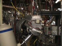
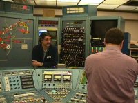
I'll show you what he-man audiophiles play with...
That SLAC? Obviously HE physics facility of some kind.
Last edited:
Crocker. The cyclotron of the Manhattan project.
I spent several years walking between the Physics and Engineering buildings
with Crocker in between, but I couldn't get a tour until many years later
when Kent English, night shift operator and audio DIYer invited us to visit
when it was down for service. Normally it ran 24/7 and was too hot inside
to allow tourists.
Kent currently works at Pass Labs.
.......
Kent currently works at Pass Labs.......
......... which runs 24/7 and is too hot inside
to allow tourists.

- Status
- Not open for further replies.
- Home
- Amplifiers
- Pass Labs
- Transformers as gain stages