Hi,
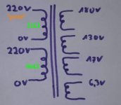
out of a box with random used parts I got a power transformer (for tube amps I suppose because of 6.3V secondary) with 4 pins on primary side, each manually labelled as "220V". Only one of these 220V labels also says "primary" and these two 220V-labellings seem to be visually seperated by a manually drawn line. Their resistances differ: between primary-called pins are 21Ω measured, the other ones show 86Ω. There is no connection in between, so there seem to be two separate windings on primary side.
(second side: 6.3V, 17V, 130V, 180V)
Are you guys familiar with such power transformers in amplifiers? Am I supposed to connect both to the 220V-grid (parallely each or treat like 2x110V: connect serially by bridging the windings to a single one)? Or is the second one actually an output winding (...like an isolating-transformer-feature)?
Thank you!
Poppy
The 21 ohm DCR winding is primary.
Do NOT connect the other "220V" 86 DCR winding in parallel, it is a secondary, probably to bridge rectify it and get around 300V DC
Your secondary description is incomplete: are they fully separate windings? Taps on the same one? Post a clear drawing.
Do NOT connect the other "220V" 86 DCR winding in parallel, it is a secondary, probably to bridge rectify it and get around 300V DC
Your secondary description is incomplete: are they fully separate windings? Taps on the same one? Post a clear drawing.
Thank you so much for helping me!The 21 ohm DCR winding is primary.
Do NOT connect the other "220V" 86 DCR winding in parallel, it is a secondary, probably to bridge rectify it and get around 300V DC
I don't know and also don't find out what you could mean with "to bridge rectify it". I mean... the use of diodes/tubes as a bridge rectifier is clear to me but what role this 2nd 220V winding could play here... Could you please name or briefly explain what you mean?
The ~300V DC you meantion are these 180V and 130V in series, right?
Or does this voltage also refer to the use of the 2nd 220V taps?
That these 220V windings are fully separate was, what I tried to explain with "no connection in between". Or do you mean something else? Here's a drawing and a foto....Your secondary description is incomplete: are they fully separate windings? Taps on the same one? Post a clear drawing.


Did you or does anybody need to know anything else, please tell.
Thank you!
From the markings on your transformer, it looks like the top left winding is a primary and the bottom left winding is a secondary.
A 220VAC secondary will give about 220*1.414= 311VDC
What are the DCR readings on the 180 and 130 secondaries ? The 180 and 130V secondaries might be there for auxilliary circuitry.
edit: a short summary of the various rectification schemes: Design Guide For Rectifier Use - Hammond
A 220VAC secondary will give about 220*1.414= 311VDC
What are the DCR readings on the 180 and 130 secondaries ? The 180 and 130V secondaries might be there for auxilliary circuitry.
edit: a short summary of the various rectification schemes: Design Guide For Rectifier Use - Hammond
Last edited:
Ah okay, now I got it. Thank you a lot! That the second 220V taps are on the same side as the primary ones on top of the fact, that these AC-voltages are both 220V lead me on this completely wrong path of thinking. Sorry, I could have come to this possibility by myself as there are no taps left on the "secondary" side. I just don't have much experience with transformers (and electronics in general). Thanks again!From the markings on your transformer, it looks like the top left winding is a primary and the bottom left winding is a secondary.
Now that you tell me I found this piece of theory very far in the back of my memory 🙄A 220VAC secondary will give about 220*1.414= 311VDC
180V: 45ΩWhat are the DCR readings on the 180 and 130 secondaries ? The 180 and 130V secondaries might be there for auxilliary circuitry.
130V: 56Ω
17V: 1.2Ω
6.3V: 0.4Ω
180V and 130V for "auxilliary circuitry"?.... Do you mean anode voltages for preamp- and phase-inverter-tubes?
Thank you!