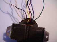
Just scavanged this transformer from an old tube radio and I don't understand its wiring.
Primary:
these were connected to voltage selector:
blue 220v
green 160v
black 145v
red 125 v
yellow 110v
but what about brown and 2 white?
Secondary:
I've checked when still working in the device
2 red 400v
2 white 6v
what about black?
I wonder if there is some kind of colour code (I read red for anode and white for heaters) or how calculate unknow values...
Attachments
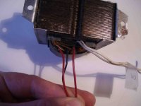
The black is probably the center tap for the red wires and was connected to ground. You can verify this with an ohm meter, the resistance between the black and either red wire should be half of the resistance of that between the two red wires.
The black is probably the center tap for the red wires and was connected to ground. You can verify this with an ohm meter, the resistance between the black and either red wire should be half of the resistance of that between the two red wires.
I measured 300ohm and 164 ohm so it is 400-0-400.
Thanks! Any idea about the other wires?
Last edited:
Are all the "primary" wires on the same winding?
Are all the secondary wires on the same winding?
Are all the secondary wires on the same winding?
Are all the "primary" wires on the same winding?
Are all the secondary wires on the same winding?
I really don't know 😕
How can I check? Are you suggesting that white unknow wires are another 6,3v secondary?
And: If blue wire is one of primary wires for 220v, which one is the other one?
Last edited:
BE VERY CAREFUL !
If there is anything in the following paragraphs that is not clear then ask again before you guess and kill yourself.
Insert each end into a separate terminal of an insulated terminal block.
The screws will ensure a reliable contact through the enamel insulation.
Use an ohm-meter to check check for continuity from all the ends to all the others.
Label each continuous set. They are one winding.
Each winding could have more than 2 ends. Sometimes an adjustment tap (or taps) just a few %, more or less, sometimes a tap at the centre (50% to either side).
Then measure the resistance of each part of the winding from tap to tap.
This will let you identify the "ends" of the windings and the intermediate tapping points.
Now select the longest "primary" tappings. Power up via a bulb tester.
Measure the voltage at each of the secondary windings and at any intermediate taps.
Last edited:
The whites could be a separate heater winding for a rectifier, either 6.3V or 5V (depending on the age of the set). Newer rectifiers tend to have an isolated heater, just like other valves, but a separate heater winding can still help with valve lifetime.
Use an ohm-meter to check check for continuity from all the ends to all the others.
Label each continuous set. They are one winding.
Each winding could have more than 2 ends. Sometimes an adjustment tap (or taps) just a few %, more or less, sometimes a tap at the centre (50% to either side).
Then measure the resistance of each part of the winding from tap to tap.
This will let you identify the "ends" of the windings and the intermediate tapping points.
Now select the longest "primary" tappings. Power up via a bulb tester.
Measure the voltage at each of the secondary windings and at any intermediate taps.
I'v e checked for continuity.
"Primary" wires: continuity between
-green
-black
-red
-yellow
-brown
no blue and no 2 white
continuity between 2 white
"seconday" wires:
continuity between 2 white
2 red wires don't have continuity at all
same for black wire
Hope this means something to you 😱
Some resistance values:
between:
brown and yellow 9
brown and red 12
brown and black 16
brown and green 21
brown and blue 59
between 2 white "primary" side 5
between 2 white "secondary" side 5
between 2 red "secondary" side 314
between one red and black 164
Once again I hope this means something to you

Attachments


Last edited:
Is blue isolated from every other wire end?
If so then it could be an electrostatic screen between primary and secondary.
Can you tell if the brown wire is wound closest to the core?
That could be the "end tapping" of the primary winding.
You need to find the other "end tapping".
It may be the blue wire showing 59r
Check the resistance from blue to all the other primary wires. Are any more than 59r?
Check from Yellow to all the other primary wires. Are any more than 59r?
Once you know that you have found the highest resistance winding then it is safe to assume it is the main connection for power in.
With all the wires still safely screwed into their separate terminals, connect the longest winding via the bulb tester to mains power.
Stand back and switch on.
Did the bulb glow, or flash, or nothing at all, or go bright. Stop there and report back.
Be very careful !!!!
The reds wires may be at very high AC voltage.
Last edited:
The bulb glows
Andrew, yes blue wire is isolated from every other wire end and yes the brown wire is wound closest to the core.
Blue and brown wires have highest resistance so I have connected them via the bulb tester to mains power and the bulb glows.
Andrew, yes blue wire is isolated from every other wire end and yes the brown wire is wound closest to the core.
Blue and brown wires have highest resistance so I have connected them via the bulb tester to mains power and the bulb glows.
Last edited:
verify coils(which color wire goes with what other wire/s) and resistances using dmm...
the coil with the lowest resistance would be the low voltage coil...
you can inject 6 to 12 volts into that coil....
measure all voltage across other coils and record them on a sheet of paper so you can look at it later...
you can try to confirm phasing of the coils by conecting coils in series, (make sure the traffo under consideration is not energized). record the connection on your paper...
try reversing the connections until you can veify that voltages are increasing with series connection and not decreasing...
armed with these information, you can then decide how the final connection of your traffo is going to be....
hope this helps....
This is not good...........I have connected them via the bulb tester to mains power and the bulb glows.
With the Bulb still in circuit:
Can you safely measure the voltage across the Brn Blu?
Can you safely measure the current through the Brn Blu?
Can you safely measure the voltage across the Brn Blu?
Can you safely measure the current through the Brn Blu?
Voltage is 183v
Current... with DMM set at 10A and at 200mA is zero, I am probably doing something wrong but I'm afraid of burning my DMM
Do not insert a multimeter into a circuit to act as an ammeter.
Instead insert a low value resistor and measure the volts drop across that resistor.
But be careful, that resistor and it's wiring is at mains voltage. Do not kill yourself.
183Vac means ~40Vac is dropped across the glowing bulb. The circuit is drawing significant mains current. There is something wrong.
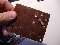
Along these same lines.... I've got a new r-core x-former (RN-20) that has the following markings for the primary windings.
0V............115V...........230V............SCN
BLK--------GRN---------RED--------YEL/GRN
I know I should be able to figure this out, but I'm confused on which pairs to tie together in a parallel fashion for 115V input. I want to make sure I've got my inputs wired correctly.
0V............115V...........230V............SCN
BLK--------GRN---------RED--------YEL/GRN
I know I should be able to figure this out, but I'm confused on which pairs to tie together in a parallel fashion for 115V input. I want to make sure I've got my inputs wired correctly.
That appears to have a single tapped primary, not two separate windings. If you have reported it correctly then 115V goes to black and green, yellow/green should be grounded and red should be safely isolated.
Red,
if the situtaton is as DF reads, then 115Vac will deliver only half the Rated VA.
However it is just possible that the manufacturer has wound the primary to deliver full VA at both 115Vac and at 230Vac.
You will need to ask the manufacturer directly.
if the situtaton is as DF reads, then 115Vac will deliver only half the Rated VA.
However it is just possible that the manufacturer has wound the primary to deliver full VA at both 115Vac and at 230Vac.
You will need to ask the manufacturer directly.
Last edited:
Thanks guys, To make things easier, here's the x-former with several pictures and markings. It does have 4-wires on the primary side so that's what's a little confusing. The listing never mentions dual primaries, so maybe it's as DF describes. 🙁 For my application 1 primary winding (115v) will provide more than enough current I believe.
- Status
- Not open for further replies.
- Home
- Amplifiers
- Power Supplies
- Transformer wiring