I'll try with no bolt and, if it's better like this, replace with a nylon one.
Hi_Q, won't the measures be influenced by the thermistor between the two primaries?
Hi_Q, won't the measures be influenced by the thermistor between the two primaries?
as you are going to measure difference between two states , NTC is irrelevant
just give it few minutes to cool of , while primary can't do the same in so short period of time
just give it few minutes to cool of , while primary can't do the same in so short period of time
I have often wondered why the washer on top does not have a couple of venting holes for better ventilation of the transformer.It can only be advantageous for ALL transformers to run cooler.
The metal washer will conduct out some heat.
The internal surface area is fairly small and the insulation is more than twice as thick with more than twice as many air layers, so there is not as much heat getting through per sq area as on the outside.
The internal surface area is fairly small and the insulation is more than twice as thick with more than twice as many air layers, so there is not as much heat getting through per sq area as on the outside.
NTC resistance is totally relevant.as you are going to measure difference between two states , NTC is irrelevant
just give it few minutes to cool of , while primary can't do the same in so short period of time
That VARIABLE resistance will ruin any result.
One would need to temporarily short out the two NTCs to make any meaningful comparison of hot:cold primary resistance.
you have to get rid of that bolt or replace that bolt with a plastic one....
Tonight, I removed the bolt and just leave the transformer on a piece of foam to insulate it from the chassis. No bolt, not tie-raps, nothing, just the transformer sitting on itis side...
After more than 3 hours, it was (once again) very hot: 62°C.
What surprised me is that the mounting bracket was very hot too though there was no direct contact between it and the transformer (I don't know if the foam I used is a good heat conductor).
The two diodes bridges are bolted to the mounting bracket (see picture on page one) but I don't know if they should warm a lot...
Bridges will get very hot
... and push additional heat to your transformer.
Would mounting the rectifier bridges on the heatsink be an option?
If you have a C-R-C config you could also choose to make the first C smaller.
The charge (current) pulse to the caps wil be smaller i.e. less stress on the transformer and less heat.
... and push additional heat to your transformer.
Would mounting the rectifier bridges on the heatsink be an option?
If you have a C-R-C config you could also choose to make the first C smaller.
The charge (current) pulse to the caps wil be smaller i.e. less stress on the transformer and less heat.
I'm not equipped to drill and machined threaded holes in the heatsinks.
I can try to bolt them on the drilled base or find small heatsink for the bridges.
Concerning the CRC, as I'm a complete newbie in the DIY world, I followed carefully what was written on the schematic. So the capacitors values should cause no problems (or it will be the same mess for everybody).
But I remember that I was a little lost when chossing the diodes bridges beacuse there was no clear reference in the BOM. Is it possible that I made a wrong choice, explaining my problems with heat?
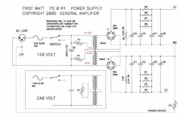
Here are the bridges I choosed: GBPC3502-E4/51 Vishay Semiconductors | Mouser
I can try to bolt them on the drilled base or find small heatsink for the bridges.
Concerning the CRC, as I'm a complete newbie in the DIY world, I followed carefully what was written on the schematic. So the capacitors values should cause no problems (or it will be the same mess for everybody).
But I remember that I was a little lost when chossing the diodes bridges beacuse there was no clear reference in the BOM. Is it possible that I made a wrong choice, explaining my problems with heat?
Here are the bridges I choosed: GBPC3502-E4/51 Vishay Semiconductors | Mouser
The metal backplate of the GBP bridge rectifier is isolated from the diodes inside.
You can attach it to a heatsink (or the Chassis floor/side) using Thermal Goop to help cool the rectifier.
But you can far lower prices than 4.6 euro.
I use three or four in each stereo amplifier.
Buy at least ten and get a bulk discount.
25A or 35A are good for many amplifiers.
You can attach it to a heatsink (or the Chassis floor/side) using Thermal Goop to help cool the rectifier.
But you can far lower prices than 4.6 euro.
I use three or four in each stereo amplifier.
Buy at least ten and get a bulk discount.
25A or 35A are good for many amplifiers.
Thanks Andrew and ZM, I'll try this.
Do you think the tight twist I made with the transformer cables could be a problem or can I leave it like this?
Do you think the tight twist I made with the transformer cables could be a problem or can I leave it like this?
Well, the transformer is still hot, even with the diode bridges bolted to the bottom plate.
Good point is that the trafo is more silent than when it was bolted to the mounting bracket, so I put a piece of foam and secured it with tie-raps.
Concerning the heat, I think I must live with it...
Good point is that the trafo is more silent than when it was bolted to the mounting bracket, so I put a piece of foam and secured it with tie-raps.
Concerning the heat, I think I must live with it...
- Status
- Not open for further replies.
- Home
- Amplifiers
- Pass Labs
- Transformer temperature