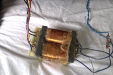
Hi, i am considering building a gainclone of some sort and i found this old transformer from a Bang and Olufson amplifier. The wireing confuses me a bit, so a thought you could help me. I know the red wire is one of the primary, and the other four others is for 4 different input settings. It is mostly the secondary wiring i am wondering about. There are two blue wires with fuses. One black in the middle and two greys. Could anyone help me explain the wires? Thanks
Attachments
Let's assume, possibly incorrectly, that the black is the centre tap of the seconday. Try measuring the resistance between black and the four other secondary wires. If you post the results we might be able to draw some conclusions.
I took it out myself, and the red wire on the left was directly attached to the power line. The four other lines are for 220, 130, 240 and 110 input.
You can check the primaries by measuring the resistances of the tappings.
You can check the secondaries by measuring the resistances of the tappings.
You can check the secondaries by measuring the resistances of the tappings.
your primary windings will have the highest resistance of all the windings...
you can get a small 6.3 volt filament transformer and feed voltages on windings and then monitor voltages on the other windings...
this will give you an idea...
how does it weigh in kgs?...
you can get a small 6.3 volt filament transformer and feed voltages on windings and then monitor voltages on the other windings...
this will give you an idea...
how does it weigh in kgs?...
I now done some meassurements. Just too clear, all the wires was attached to a switch that switched between 220,130,240,110. Now i dont know witch wires too use for 240 volts (EU). How can i figure that out?
Meassurements.
Secondary side:
There is a resistance of 02.0 (200) ohm, between the two grey wires. They seem too connect with nothing else.
Black-Blue: 00.3
Blue-Blue: 00.6
Primary side:
There is resistance between yellow-black and brown.
Black-Brown: 05.2
Black-Yellow: 06.4
Brown-Yellow: 01.0
There is resistance between red and blue.
Red-Blue: 05.2
(The red wire was directly attachted too one of the input wires)
OK so we have the windings. GREY - GREY is one winding. BLUE - BLACK - BLUE is another winding that looks like it's centre tapped. The Left Hand side looks like a multi-voltage primary. As Red - Blue is the same as Black - Brown I would assume that these are 2 x 110V primaries, one of the primaries has extra turns for possibly 240V.
Now we need to sort out the phasing of the windings. Best thing for that is a small transformer outputting a few volts AC.
Let's assume that the Primaries are Black - Yellow and Red - Blue. If you connect Yellow and Red together and connect a small AC voltage across Black and Blue, you should see a small voltage across Grey - Grey. If you get nothing then the primaries are probably in anti-phase. Try connecting Black and Red and the AC voltage across Yellow and Blue, the higher of the two voltages across Grey - Grey will reveal the phase of the primaries.
If you get ridiculously low voltages that don't seem to make any sense, try connecting say 5V AC across Grey to Grey and then measure the voltages across Blue - Blue, Red - Blue and Black Brown.
I'm assuming here that not many transformers these days output less than 5V.
There will then be several known factors.
Vp1, Vp2, Vs1 and Vs2. The ratio between them will NEVER change, that is transformer theory.
If you have put 5V across S1 (Grey - Grey) and measure 50V across P1, we know that Np1/Ns1 = 10.
We can use these figures to determine the voltages that the transformer can provide, this is not exact but it's a safe starting point.
Where can you find these kinds of few volts AC transformers. Is there any easy way to test these things?OK so we have the windings. GREY - GREY is one winding. BLUE - BLACK - BLUE is another winding that looks like it's centre tapped. The Left Hand side looks like a multi-voltage primary. As Red - Blue is the same as Black - Brown I would assume that these are 2 x 110V primaries, one of the primaries has extra turns for possibly 240V.
Now we need to sort out the phasing of the windings. Best thing for that is a small transformer outputting a few volts AC.
Let's assume that the Primaries are Black - Yellow and Red - Blue. If you connect Yellow and Red together and connect a small AC voltage across Black and Blue, you should see a small voltage across Grey - Grey. If you get nothing then the primaries are probably in anti-phase. Try connecting Black and Red and the AC voltage across Yellow and Blue, the higher of the two voltages across Grey - Grey will reveal the phase of the primaries.
OK let's carry on. If we connected 5V AC across Grey-Grey and measured 50V across P1 and 55V across P2, we now need to find out the correct phasing of P1 and P2. Simply connect them in series, if the phasing is correct the voltages will add, if they are incorrect they will subtract. Once you have the maximum voltage coming out of the primaries you have located the 240V primary configuration. You can drop back to the 220V configuration if you are intending on using the transformer at 110V.
Let's sort out the phasing
Use a mains bulb tester.
If any wire is connected up wrongly the bulb lights up to tell you "WRONG" !
Use a mains bulb tester.
If any wire is connected up wrongly the bulb lights up to tell you "WRONG" !
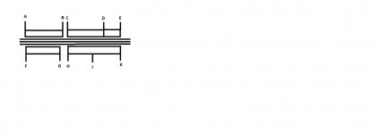
OK I've drawn a drawing
Lets look at my drawing.
A-B are your P1
C-D are your P2 with the additional bit E
F-G are your S1 Grey - Grey
H-J-K are your S2 Blue-Black-Blue
Connecting B-C should give you the maximum voltage across A-E.
For 240V operation I would connect B-C and then 240V across A-E, D is not connected.
For 220V operation I would connect B-C and then 220V across A-D, E is not connected.
For 110V operation I would connect A-C and B-D and connect 110V across A-B, E is not connected.
Attachments
Use a mains bulb tester.
If any wire is connected up wrongly the bulb lights up to tell you "WRONG" !
I'm only suggesting testing at 5V bulb tester doesn't work at these voltages.
If you don't know what a 5V transformer is we can hardly help you. You can use any low voltage transformer, 6V, 9V anything handy. It MUST be AC.
I finally found a transformer and testet the things. I tried connecting them in all sorts of ways, but the one with the biggest difference was PRIMARY-BLUE connected with PRIMARY-BLACK, sending the current through PRIMARY-YELLOW and PRIMARY-RED. This setup made the output voltage 8 times smaller. This would make the output voltage at 28.75. All other setups would not get above 4 times smaller. I am still a little confused why a should only meassure on the grey wires and not the blue-black-blue ones? Thanks againLets look at my drawing.
A-B are your P1
C-D are your P2 with the additional bit E
F-G are your S1 Grey - Grey
H-J-K are your S2 Blue-Black-Blue
Connecting B-C should give you the maximum voltage across A-E.
For 240V operation I would connect B-C and then 240V across A-E, D is not connected.
For 220V operation I would connect B-C and then 220V across A-D, E is not connected.
For 110V operation I would connect A-C and B-D and connect 110V across A-B, E is not connected.
Also how low do i want the output to be. The transformer is at least 30-40 years old, so perhaps the 240 volt output voltage was lower than i need it today??
30 years ago we still had 110V and 240V. We are just using the secondaries to measure Np/Ns. Once we have established the secondaries we can move on to seeing what the transformer can be used for.
Last edited:
- Status
- Not open for further replies.
- Home
- Amplifiers
- Power Supplies
- Transformer specs?