I'd push the OPTs to the back far corners & drop the terminals to the back of the enclosure...Although flux leakage from a toroid is less that of the conventional "E I" laminate, distance is everything.
I know top mounted terminals are "cool looking" & all, but the techno-look detracts from the clean look...
------------------------------------------------------------------Rick.....
I know top mounted terminals are "cool looking" & all, but the techno-look detracts from the clean look...
------------------------------------------------------------------Rick.....
I have filter chokes in the power supply. Right now they are pretty close to the PT. What is the spacing off those relative to other things?
Do not worry about chokes and power transformers coupling to each other.
The capacitors after the choke takes care of the reasonably small coupled signal.
Instead, worry about the choke coupling to the output transformer,
and as you mentioned, the power transformer coupling to the output transformer.
Do not forget to use the proper orientation between the output transformers and the other the other parts that produce magnetic fields.
Usually 90 degrees is right, especially if they are in line, but if they are on opposite corners, not adjacent corners, 90 degrees may not be optimum.
Toroids make it difficult to determine, but twist all the toroid leads, they are probably the major contributor of external fields, especially if you use capacitor input filtering of any DC supplies.
Be sure . . . do Not use magnetic steel chassis.
they will couple hum fields across several feet of a big chassis; even worse on a medium or small chassis.
If aluminum is too weak to support the parts, cut a second aluminum plate, and make a sandwich with the aluminum chassis.
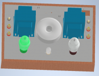
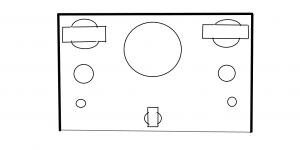
Besides the OPTs in the back corners, the toroid between the two, the tubes at the outsides edges ( I have two drivers pictured here, four tubes total)
Put the choke underside towards the front..chokes create the worst of stray fields.
-----------------------------------------------------------------Rick..........
Put the choke underside towards the front..chokes create the worst of stray fields.
-----------------------------------------------------------------Rick..........
Attachments
If possible, do a wooden mockup, and put 60Hz signals to one part, and see how well it couples to the output transformer.
Connect a scope to the output transformer primary (more voltage, easy to see, versus connecting the scope to the secondary).
Now, rotate the part that has the 60Hz applied, look for a null at some rotational degree..
Connect a scope to the output transformer primary (more voltage, easy to see, versus connecting the scope to the secondary).
Now, rotate the part that has the 60Hz applied, look for a null at some rotational degree..
I have one driver tube. Should I put it to on side off the chassis? I am assuming your answer is yes.Besides the OPTs in the back corners, the toroid between the two, the tubes at the outsides edges ( I have two drivers pictured here, four tubes total)
Put the choke underside towards the front..chokes create the worst of stray fields.
-----------------------------------------------------------------Rick..........
However that will force me to wire the driver tube to the other side output tube which will cross the PT and Choke area.
Would you recommend 2 driver tubes (not use both sections of the driver triode) to keep each channel divided and keep the middle with the PS components>
Also, the RH807 PS is a capacitor input filter with a choke section after? Does that change the concern as a choke input would have alot more mag field or not?
All other things being equal . . .
Choke input filters have the most magnetic spray.
But a cap input filter, CLC with a 1uF cap, 5H choke, 100uF cap will also have quite a bit of magnetic spray.
A cap input filter, CLC with a 10uF cap, 5H choke, 100uF cap will have quite a bit less magnetic spray, than the one that had a 1uF input cap.
However, the B+ Ground loop is largest for the CLC 10uF input cap example above.
Even if you do take care of the choke magnetic spray; but do not take proper care of the 10uF cap ground loop, you will get lots of hum in your amplifier.
My PS is full wave diode with CT. 47uf input cap. Then 7mh + 100uf filter to each B+ channel.
Tips on avoiding B+ ground loop issues would be appreciated. Or if there is a thread on that let me know to avoid redundancy.
I really appreciate you guys help!
Tips on avoiding B+ ground loop issues would be appreciated. Or if there is a thread on that let me know to avoid redundancy.
I really appreciate you guys help!
I'm going to make some waves by putting this out there, but do you absolutely have to use the toroidal PT? I would expect you to run into magnetic coupling between your PT and output transformers unless you got different end covers and rotated the 90 degrees so the cores point up and down. Yes, toroidal transformers are reputed for being quieter, but an EI power transformer will have a region reasonably close to it where the magnetic field lines are rather predictable and straight, and that's a nice place to put your output iron.
I'm going to make some waves by putting this out there, but do you absolutely have to use the toroidal PT?
I don't, but I have it already. So I will probably not discard it and buy another PT before I try the one I have. They seem to somewhat popular and from many pics around they seem to be used close to the OT's.
I thought you were going to the question do I have to use the chokes?
If the choke is 7mH, I would also question that choice. 7H would be typical/useful. Since you have a cap input filter, the choke is unlikely to cause issues.
If the choke is 7mH, I would also question that choice. 7H would be typical/useful. Since you have a cap input filter, the choke is unlikely to cause issues.
Its 7H. (not mh). At 7H is your opinion that it will not likely cause issues?
My opinion says you need to measure the interference, either with a scope, or with a loudspeaker (listen).
You have a 47uF first filter cap driven by the diodes.
At 100mA (0.1A) current, the ripple voltage at the 47uF is aproximately the capacitive reactance times the current.
Xc = 1/(2 x pi x 120Hz x 47uF)
Xc = 28.2 Ohms
0.1A x 28.2 Ohms = 2.82V peak to peak ripple. That is 1Vrms.
Apply 120Hz 1Vrms across the choke, and that will simulate the magnetic field from the choke in the working power supply.
If you have a 50 Ohm signal generator, and set it to 2Vrms, that will be close enough to 1Vrms across the 28 Ohms Xc choke.
The problem is that the upper harmonics of the transient capacitor current in a working power supply will not be there in the choke when you apply a 120Hz sine wave.
So use a 120Hz triangle wave, or a 120Hz square wave.
Connect the output transformer 8 Ohm tap to an 8 Ohm loudspeaker. Put your ear near the loudspeaker and listen.
Or connect the scope 10x probe across the output transformer primary.
Then move the choke and output transformer near each other, and rotate one of them slowly through 180 degrees, to find the maximum and minimum hum according to the rotation orientation.
Last edited:
Thank you! I can and will do that.
Apply 120Hz 1Vrms across the choke, and that will simulate the magnetic field from the choke in the working power supply.
If you have a 50 Ohm signal generator, and set it to 2Vrms, that will be close enough to 1Vrms across the 28 Ohms Xc choke.
The problem is that the upper harmonics of the transient capacitor current in a working power supply will not be there in the choke when you apply a 120Hz sine wave.
So use a 120Hz triangle wave, or a 120Hz square wave.
Connect the output transformer 8 Ohm tap to an 8 Ohm loudspeaker. Put your ear near the loudspeaker and listen.
Or connect the scope 10x probe across the output transformer primary.
Then move the choke and output transformer near each other, and rotate one of them slowly through 180 degrees, to find the maximum and minimum hum according to the rotation orientation.
- Home
- Amplifiers
- Tubes / Valves
- Transformer spacing