You had two secondaries, which were actually one secondary. Now you seem to have three grounds, which are actually one ground. You even have wires for one ground carefully stepping over wires for another ground.
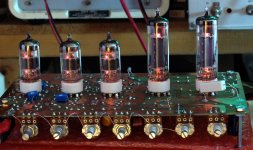
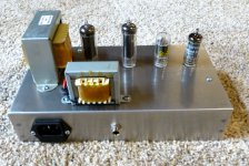
Here is the circuit of a working guitar amp that does what you want. (first schematic, first two pictures)
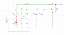
It uses a Triad FD8-120 120/240 to 120 volt isolation transformer that feeds a FW bridge and a FW doubler simultaneously to produce 165 volts for the tube heaters and output tube screen grids and 330 volts for the rest of the amp's B+ voltage. R34 is not used, but available so that 150 mA output tube heaters could be used.
I used a 100 VA transformer because this amp produces 20 watts of output power power and consumes too much power for a 50 VA Triad N68-X.
The output tubes are 45B5/UL85 and the preamp tubes are 26AQ6/UCC85. A lot of the solid state stuff was eliminated in the final build which still had too much gain and was too microphonic. It will be revisited in the future.
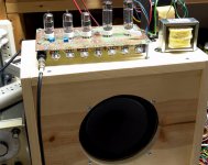
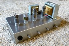
I also have a smaller 4 watt version with 100 mA heater 32ET5's, an 18FW6 and an 18FY6 that runs from a Triad N68-X, but the 150 mA, 50L6 / dual 12AX7 version made the N68-X rather warm. (second schematic, 3rd and 4th pictures)
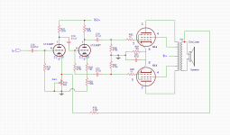
Transformer heat can be reduced by running the heaters from unfiltered full wave rectified DC which has the same energy and power consumption as the raw AC from the transformer. You would use 125 to 130 volts worth of series connected heaters for this type of circuit. This is shown in the second schematic. An isolation diode, D5 is needed so that the filter for B+ does not apply to the heater circuit. A doubler can also be connected to this circuit. R4 reduces peak transformer current thus reducing heat. It also provides some voltage sag somewhat simulating a tube rectifier.
Note that 50L6's are really 6W6GT's with a 50 volt heater. They will eat 330 volts on their plates and happily put out 10 watts in push pull, but the screen grids MUST be operated in the 120 volt range.
It uses a Triad FD8-120 120/240 to 120 volt isolation transformer that feeds a FW bridge and a FW doubler simultaneously to produce 165 volts for the tube heaters and output tube screen grids and 330 volts for the rest of the amp's B+ voltage. R34 is not used, but available so that 150 mA output tube heaters could be used.
I used a 100 VA transformer because this amp produces 20 watts of output power power and consumes too much power for a 50 VA Triad N68-X.
The output tubes are 45B5/UL85 and the preamp tubes are 26AQ6/UCC85. A lot of the solid state stuff was eliminated in the final build which still had too much gain and was too microphonic. It will be revisited in the future.
I also have a smaller 4 watt version with 100 mA heater 32ET5's, an 18FW6 and an 18FY6 that runs from a Triad N68-X, but the 150 mA, 50L6 / dual 12AX7 version made the N68-X rather warm. (second schematic, 3rd and 4th pictures)
Transformer heat can be reduced by running the heaters from unfiltered full wave rectified DC which has the same energy and power consumption as the raw AC from the transformer. You would use 125 to 130 volts worth of series connected heaters for this type of circuit. This is shown in the second schematic. An isolation diode, D5 is needed so that the filter for B+ does not apply to the heater circuit. A doubler can also be connected to this circuit. R4 reduces peak transformer current thus reducing heat. It also provides some voltage sag somewhat simulating a tube rectifier.
Note that 50L6's are really 6W6GT's with a 50 volt heater. They will eat 330 volts on their plates and happily put out 10 watts in push pull, but the screen grids MUST be operated in the 120 volt range.
Attachments
Thanks a lot that is awesome, it looks like the bridges are in series rather than parallel, I will have to look at that closer. I am thinking of building a PP 50L6 amp so the 6W6 info is good to have. The specs on the 50L6 tubes say 200V but I see the 6W6 says 300. You are running them at 330V? 660V for the PP pair to get 10W?
I have a question about the PP OT.
If I am running 50L6 and the OT is 3.5K:8 would the following be correct for these other configurations?
PP 7K:8
PSE 1.7K:8
I have a question about the PP OT.
If I am running 50L6 and the OT is 3.5K:8 would the following be correct for these other configurations?
PP 7K:8
PSE 1.7K:8
it looks like the bridges are in series rather than parallel, I will have to look at that closer.
Not really. There are three independent circuits wired in parallel but sharing D1 and D2. There are two voltage doublers sharing C20. The power transformer secondary must connect to the circuit in only these two places. No ground (CT) connection can be used or smoke will happen!
Diodes D1 through D4 form a conventional bridge rectifier. The output is connected to C24 as in any standard bridge circuit, assuming the other diodes and caps are not there.
Diodes D2, and D6 along with C21 and C20 form a standard voltage doubler. This is all that is required if the load is light, but we can improve it by adding a second voltage doubler operating out of phase with the first. Transformers don't like loads that draw unequal currents on each half cycle, so the second doubler fixes that and greatly reduces the output ripple. It is D1, D8, C22 and C20. D5 and D7 may not be required, but I haven't tested or simulated this.
C21, C22, C23 and C24 can be 250 volt caps. C20 must be a 400 volt cap.
You are running them at 330V?
Yes, 330 volts of B+ (more like 340 on our high line voltage) from a power supply like that shown. The screen voltage must be in the 110 to 125 volt range to do this. I use the bridge rectified 165 - 170 volt source through a resistor to get 125 at idle which drops below 100 volts when overdriven in a guitar application. For HiFi applications you want a more stable G2 source to reduce distortion. Do not attempt triode connection at 330 volts!
660V for the PP pair to get 10W?
The idle plate voltage will be around 330 volts. Each plate will swing from about 60 volts to about 600 volts at full power. Over 10 watts is easy with AB1, somewhere around 30 watts is possible if AB2 is used when G1 is driven positive. I used a 6600 ohm OPT for my testing.
50L6 and the OT is 3.5K:8 would the following be correct
I have not experimented with PSE, but if one tube likes 1.5K, then two would work with half that, or 1.75K. 7K would be fine for a push pull pair, you might lose a watt but life will be easier on the tubes.........
Note that My experiments have used mosfets driving the grids way into positive voltage territory and I have really pushed some of these little tubes far beyond where we believed they could safely go without issue. The "10 watt" number was observed by watching where the grid went positive.
I have seen 40 watts at 5% distortion flow from a pair of 6W6GT's on 425 volts for over an hour continuously with no red glow or other ill effects. I have also seen 30 watts at 3% come out of a pair of 50C5's on 340 volts, and 40 watts on 400 volts. I didn't leave that one running for more than a few minutes though.
When you run these little tubes on high plate voltages you must reduce the idle current to get the plate dissipation down close to the specs. I ran the 6W6GT's at 20 mA and the 50C5's at 15 mA.
Very helpful information. I am looking at building a small Guitar/Bass amp and I have come up with the attached 12L6 PP base schematic. I have all the tubes and parts (Except the OT). Any advise to improve would be appreciated, but keep it simple, I'm a noob.
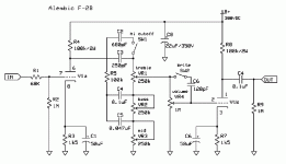
Still don't have the tone part yet, but I am going to use the Alembic F2B schematic to build this out. I am also thinking about adding a 12AL5 for some soft tube clipping. Might sound good with Guitar and bass. Would I need another 12AX7 to add the tone circuit? I don't know if I would get enough gain from just the 1st 12AX7 half before the splitter. I never built anything more complicated than a simple SE amp yet.
I settled on the 12V heater tubes because I have a regulated 12V supply 2A. I have 2 6X4 Rectifiers also for the B+. Was going to use the triad I have which will give me 188.5V for B+. I can double it for 377V then use the 188.5 for B2+.
Attachments
Last edited:
- Status
- Not open for further replies.
- Home
- Amplifiers
- Power Supplies
- Transformer secondary parallel out question