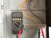
Hi everyone, I have salvaged an old chassis complete with transformer. I have attached pics of the ac voltages. I plan on caseing my Pass B1 buffer which requires 18 - 24 DC. The buffer has 2 x 15000uf 35 volt filter caps and the bridge rectifier is a d5sba20.
My knowledge of equations is limited, but this is a great opportunity for me to learn. Help with this is much appreciated.
My knowledge of equations is limited, but this is a great opportunity for me to learn. Help with this is much appreciated.
No, but you may be a bit too impatient.Is this a silly question?
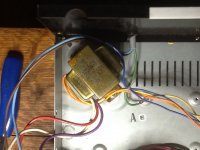
You also need to know the current capacity of each winding. The simplest method is to measure the gauge of each wire, but it requires that the output wires are directly the enameled copper, otherwise you'll have to resort to another technique, involving the measurement of the windings resistance.
That looks impossible, unless it is a very low power PSU.Thanks Elvee, just nervous. I measured R between yel, org and blu combinations then divided voltages by R: Currents = Yellow 3.3 A, Org 3 A, Blu 4.5 A.
You have to measure using 4 wire technique, with a test current of 100mA or 1A
Ok, so I have done some reading and come up with,
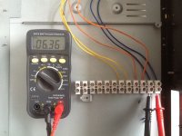
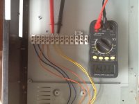
I hooked up one pair of the secondary wires together, organge and blue, 23.3 volts + 6.36 volts. The measured the AC voltage at the free ends. This gave me 17 volts.
For rectifier,
If multiply 17 volts by 1.4 I get 23.8 volts, - 1.4 = 22.4volts
Does this sound about wright?
I hooked up one pair of the secondary wires together, organge and blue, 23.3 volts + 6.36 volts. The measured the AC voltage at the free ends. This gave me 17 volts.
For rectifier,
If multiply 17 volts by 1.4 I get 23.8 volts, - 1.4 = 22.4volts
Does this sound about wright?
The B1 uses virtually no current, something in the order of 10mA so your transformer will be fine.
The 6V winding is too low so I'd dis-regard that one.
The 24V winding would produce about 35V after rectification which is on the limit of the caps. However it would be OK.
The 12V winding would produce about 16V after rectification which would also be fine.
The B1 will operate from anything between about 9V to about 40V. The caps in your setup will reduce the maximum voltage to 35V.
Last edited:
22.4 is the RMS AC voltage.
If the diode bridge had no losses then this would convert to 22.4 x 1.414 = 31.6 VDC.
However, in a bridge rectifier you will always have 2 diodes in series with this supply, each diode will drop approximately 0.7V.
So your final DC voltage will be approximately 31.6 - 0.7 - 0.7 = 30.2V DC
If the diode bridge had no losses then this would convert to 22.4 x 1.414 = 31.6 VDC.
However, in a bridge rectifier you will always have 2 diodes in series with this supply, each diode will drop approximately 0.7V.
So your final DC voltage will be approximately 31.6 - 0.7 - 0.7 = 30.2V DC
In order to get some meaningful measurements you will need to put a load on your power supply.
Something close to what the power supply will eventually be powering.
If the B1 takes 10mA and you are expecting a voltage of about 30V, you can use a resistor of 3K3 0.6W will be fine.
Something close to what the power supply will eventually be powering.
If the B1 takes 10mA and you are expecting a voltage of about 30V, you can use a resistor of 3K3 0.6W will be fine.
Thanks, Can I ask how you came to that load. 30 v / 10 ma?
Coincidentally this thread just popped up, time for some reading. Thanks guys
http://www.diyaudio.com/forums/chip-amps/128561-chip-amp-power-supply-beginners-guide.html
Coincidentally this thread just popped up, time for some reading. Thanks guys
http://www.diyaudio.com/forums/chip-amps/128561-chip-amp-power-supply-beginners-guide.html
Last edited:
The B1 uses BL grade jFETs.
These have an Idss of 6mA to 12mA
The B1 runs the jFETs at an Id that is virtually equal to their Idss.
Expect a two channel B1 to draw a current of 12mA to 24mA depending on where in the Idss range the selected jFETs have come from.
The B1 runs at a nominal 18V, increasing the supply to >>20V will increase the jFET Id and very significantly increase the device dissipation.
They will run hot if taken too high, particularly those with an Idss near the top end of BL grade.
- Status
- This old topic is closed. If you want to reopen this topic, contact a moderator using the "Report Post" button.
- Home
- Amplifiers
- Power Supplies
- Transformer secondary calculations.